HD Monitor HDモニター HDM-70WV HDM-70WV/S O perat ing I ns t ruc t ions Before operating the system, please read this manual thoroughly and remain it for future reference. 取扱説明書 ご使用の前に必ずこの取扱説明書をお読みください。 なお、取扱説明書は必要に応じてご覧になれるよう 大切に保管してください。 Volume1, 1st edition Ver.1.
WARNING For the customers in the U.S.A. To reduce the risk of fire or electric shock,do not expose this apparatus to rain or moisture. This equipment has been tested and found to comply with the limits for a Class A digital device, pursuant to Part 15 of the FCC Rules. These limits are designed to provide reasonable protection against harmful interference when the equipment is operated in a commercial environment.
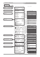
Contents 目次 HD Monitor HDM-70WV HDM-70WV 目次 Names and Functions of Parts 4 各部名称と働き Front panel 4 Rear panel 10 Left side, Right side,Upper and Bottom 13 フロントパネル リアパネル 左側面,右側面,上面,下面, Fixing 14 Connection 20 Adjustments and Settings 26 Accessories 38 Outside View and Dimensions 39 Specifications 40 組み立て方法 接続方法 調整・設定 付属品 外形寸法図 仕様 03
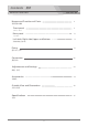
Names and Functions of Parts 各部名称と働き HD Monitor HDM-70WV HDM-70WV 各部名称と働き Front panel フロントパネル Screen (with Bezel and Protector) The display screen is 7.0 inches LCD with the bezel( open size : 152.4mm 91.4mm). And the screen is covered with the protector(181.4mm 100.6mm). スクリーンは 7インチ液晶で、画面寸法は 152.4mm 92.4mm です。 プロテクターで保護されています。 Front TALLY Indicator LED (RED and GREEN) Lights up to RED or GREEN when the tally signal is input to the TALLY IN 1 connector.
HD Monitor HDM-70WV Names and Functions of Parts Front panel フロントパネル POWER Indicator Lights up when the POWER switch is turned on and the power is supplied to the DC IN connector. POWER スイッチが ON のとき点灯します。 VOLUME / PUSH SELECT switch By rotating the knob adjust the audio volume level of the monitor speaker (when the headphone is disconnected) or the headphone level connected to the jack( ).
HD Monitor HDM-70WV Names and Functions of Parts Front panel フロントパネル RGB switch Selects the image (Blue only, GREEN only, RED only, full color) in sequence. ブルーオンリー→グリーンオンリー→レッドオンリー→フルカラー→の順に切り替えます。 → Blue only ↓ GREEN only ↓ RED only ↓ full color( LED off ) ↓ MONO switch Selects the image, monochrome( LED on ) or color. 画面表示のカラー, モノクロ の切替えをします。 UTIL select switch Selects the utility function in sequence as follows.
HD Monitor HDM-70WV Names and Functions of Parts Front panel フロントパネル (2) Rotating knob adjusts(confirms) a value. SHARPNESS LED LED LED (1) Pressing knob selects USER setting and LED lights on. BRIGHT level control volume and select switch / LED Indicator Pressing the knob selects the USER setting or STANDARD(default) setting. When USER setting is selected( LED indicator lights on ), rotating this knob adjusts the brightness.
HD Monitor HDM-70WV Operating the Menus Names and Functions of Parts メニューの操作 Menu Display メニューの表示 Press the MENU button. The menu list is displayed on the screen. Press Menu list INFO PICTURE [1080 i/60] MARKER AUDIO WAVEFORM VECTORSCOPE ZEBRA Menu Setting メニューの設定 SETUP INPUT VIDEO FORMAT VERSION SDI-MAIN 1080 i/60 ### [ON] [ON] [ON] [OFF] Menu Selection and fixing By rotating the ENTER knob button move the cursor to the desired item position and then the submenu list is displayed.
HD Monitor HDM-70WV MENU list メニュー項目 <Submenu &[factory setting] > 設定項目 <MENU> メニュー INFO [1080 i/60] ピクチャー カラー マーカー [ON] RETURN LEVEL METER [ON] DISPLAY CHANNELS [8] DISP TYPE [OVERLAP] HEADROOM START -20dB] HEADROOM END [-6dB] FRONT VOLUME [15] FRONT LEFT CH [1CH] FRONT RIGHT CH [2CH] REAR LEFT CH [1CH] REAR RIGHT CH [2CH] [ON] RETURN [ON] WAVEFORM DISP TYPE [OVERLAY] [95.0%] Y OVER LIMIT Y UNDER LIMIT [0.
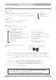
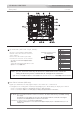
HD Monitor HDM-70WV Names and Functions of Parts Rear panel リアパネル I/F connector ( HD D-sub 15-pin, female ) HD D-sub 15-pin Connector Pin Assignment Used for connecting the HDM-70WV instead of the VF to the VF connector of the camera. Connect the HD D-sub 15-pin cable from the VF connector of the camera.
HD Monitor HDM-70WV Names and Functions of Parts Rear panel リアパネル TALLY 1 connector (BNC) Input a tally signal to light up the front and the rear tally indicators. The front tally indicator lights up to RED or GREEN according to the voltage of the tally signal. (RED : 4-5V, GREEN : 2-4V ). The rear tally indicator lights up only to RED.
HD Monitor HDM-70WV Names and Functions of Parts Rear panel リアパネル RET OUT (return control signal output) connector (8-pin) Connect to the zoom lens of a camcorder with the supplied 8-pin zoom lens remote control cable(1 m). Used for the lens zooming and the recording start/stop of the VTR. ズームリモコン用リモートケーブル(付属)を接続してカムコーダー(レンズ)へ リモート信号(リターン切替、 ズーミング、VTR録画/停止) を出力します。 AUDIO OUT 1/2 (XLR 3-pin 2) Outputs the de-embedded analog audio signals from the HD/SD-SDI input signal to the SDI IN I connector.
HD Monitor HDM-70WV Names and Functions of Parts Left side, Right side, Upper & Bottom 左側面. 右側面 および 上面, 底面 Left side Right side Bottom Upper Headphone jack (φ 6.3 stereo jack) Connect a headphone to monitor the audio signal selected by pressing the VOLUME/PUSH SELECT switch. ヘッドホンを接続してオーディオ出力をモニターします。VOLUME/PUSH SELECT (ボリューム/切替)スイッチを押して選択した 音声信号をモニターします。 Screw holes (2-w1/4(left, right)) Used to fix the supplied tilt arm stay.
Fixing 組み立て方法 HDM-70WV 組み立て方法 HD Monitor HDM-70WV VF Tilt Arm Stay Fixing アームの取り付け方法 Make sure to disconnect the connectors before fixing up. 組み立ては、必ず入出力コネクタの配線をはずしてから行ってください。 1 Prepare the supplied VF Tilt Arm Stay, five arm stay screws and washers (one is used to fix up to a camera), and two combination washers, .
HD Monitor HDM-70WV Fixing VF Tilt Arm Stay Fixing 3 アームの取り付け方法 Insert the VF Arm Stay into the gap between the combination washer and the screw, and tighten the arm stay screw with the rubber washer.
HD Monitor HDM-70WV/S Fixing Mounting on Swing Arm ( for HDM-70WV/S only ) スイングアームへの取り付け方法 Make sure to disconnect the connectors before fixing up. 組み立ては、必ず入出力コネクタの配線をはずしてから行ってください。 1 Prepare a tripod and remove the tripod base and the camera plate. Tripod Base Screws(supplied) 三脚ベースネジ 三脚を用意し、三脚ベース、カメラプレートを外します。 or Tripod Base 三脚ベース Swing Arm (supplied) スイングアーム part for mountig HDM-70WV HDM-70WV取付部 2 Camera Plate カメラプレート Fix up the tripod base and the camera plate to the Swing Arm.
HD Monitor HDM-70WV/S Fixing Mounting on Swing Arm ( for HDM-70WV/S only ) 3 スイングアームへの取り付け方法 Fix up the Arm on the tripod and mount HDM-70WV on it. アームを三脚に固定し、HDM-70WVをマウントします。 VF tilt arm stay NOTE : Make sure to mount HDM-70WV folding the Swing Arm as shown in Fig. 注意 : HDM-70WVをマウントする場合は、図のように、 必ずスイングアームを折りたたんだ状態で 行ってください。 3-1 w 1/4 arm stay screw In case of using arm stay fix with w 1/4 arm stay screw.
HD Monitor HDM-70WV Fixing Location Stand Removal and Fixing 1 ロケ用スタンドの脱着方法 Loosen/tighten four screws on the bottom to remove/fix.
HD Monitor HDM-70WV/S Fixing Hood Mounting ( for HDM-70WV/S only ) 1 フードの取り付け方法 Prepare the supplied Hood and four screws. フードと固定ネジ4本を用意します。 Hood 2 Tighten four screws on the left and right side.
Connection 接続方法 HD Monitor HDM-70WV HDM-70WV 接続方法 Power Supply Connection 電源の接続方法 Make sure to turn off the POWER switch of each unit before connecting. 接続する前には、必ず各機器の電源スイッチをOFFにしてください。 1 Connect the supplied AC adaptor to the DC IN 12V connector( XLR 4-pin) on the rear panel.
HD Monitor HDM-70WV Connection HD/SD-SDI video signal connection 1 HD/SD-SDIビデオ信号の接続 Connect the HD/SD-SDI output signal from a camcorder to the SDI (HD/SD) IN 1 connector. Connect the SDI (HD/SD) 1 OUT connector to the HD/SD-SDI input connector of a switcher, etc. Connect the HD/SD-SDI return video signal from a switcher, etc. to the RET IN connector.
HD Monitor HDM-70WV Connection HD/SD Analog Component Video Signal Connection 1 HD/SDアナログコンポーネント信号の接続 Connect the HD/SD analog component video output signal from a camcorder to the ANALOG Y/ PB/ PR connectors with BNC cables. ANALOG Y/PB/PR 入力コネクタへカムコーダーのHDコンポーネント 出力コネクタから接続します。 ANALOG Y PB PR BNC from Camcorder カムコーダー HD/SD analog component video signal output アナログコンポーネント出力 2 In case of connecting to the VF connector of the camcorder : Connect the HDM-70WV instead of the VF of the camcorder.
HD Monitor HDM-70WV Connection Audio Signal Connection 1 音声信号の接続 Connect the AUDIO OUT 1/2 connectors ( XLR 3-pin ) to a mixer, etc. with a XLR 3-pin cable. AUDIO IOUT 1/2 コネクタ からミキサー等へキャノン3ピンケーブルで接続します。 AUDIO OUT 1 Monitor speaker モニタースピーカー AUDIO OUT 2 XLR 3-pin 2 to Mixer, etc. ミキサー, 等 In case of using a headphone, connect the headphone jack to the headphone. ヘッドホンを使用する場合は、ヘッドホンジャックへ接続します。 Headphone jack (φ 6.
HD Monitor HDM-70WV Connection TALLY Signal Connection 1 タリー信号の接続 Connect the tally output signal from a camcorder, a camera adaptor, switcher, etc. to the TALLY 1 connector or TALLY 2 connector.
HD Monitor HDM-70WV Connection Zoom Remote Controller (RETURN Controller) Connection ズームリモコンの接続 Using a zoom remote controller, the switching the input signal, from the HD/SD-SDI signal to the RETURN signal, is enabled by pressing the RET(return) button , besides the zooming of the lens and the recording start/stop of the VTR.
Adjustments and Settings 調整・設定 HD Monitor HDM-70WV HDM-70WV 調整・設定 Video Signal Setting and Adjustment ビデオ信号の設定・調整 USER preset functions, etc. work when the video signal is input. 注意 : 各機能は、信号が入力されているとき動作、操作ができます。 信号が入力されているとき操作,設定されていた機能は、信号が遮断されると操作できなくなります。 1 Input signal Select 入力の選択 Select a input signal connected to the input connector by pressing INPUT select switch in sequence. And the selected signal and the video format are displayed on the screen.
HD Monitor HDM-70WV Adjustments and Settings Video Signal Setting and Adjustment ビデオ信号の設定・調整 3 BRIGHT/CONTRAST/SHARPNESS Adjustment 明るさ/コントラスト/シャープネスの調整 (1)By pressing each knob select the USER preset memory. Then the indicator LED lights on. (2)By rotating the knob adjust each setting. The each setting ranges from 0 to 100. When the LED lights off, each setting is set to STANDARD(default setting value).
HD Monitor HDM-70WV Adjustments and Settings UTILITY Function - User Setting ユーティリティー機能 - ユーザー設定 メニューの操作 - ユーザー設定 の方法 5 Menu Operation - USER Setting By pressing the MENU button, and by rotating and pressing the ENTER knob set the functions. MENUボタン、ENTERツマミで各ファンクションを設定します。 5-1 Menu Display メニューの表示 5-1 Press Press the MENU button, and the menu list is displayed on the screen.
HD Monitor HDM-70WV Adjustments and Settings User Function Setting 6 User Function/Utility Setting ユーザー設定 ユーザーファンクション/ユーテティリティー(測定器機能)の設定 On the MENU, adjust and set the USER setting of the each function. By pressing the function button on the front panel selecting the USER mode, the set items function. 6-1 Zebra ゼブラ [default setting] デフォルト設定値 Menu for ZEBRA ZEBRA [OFF] ZEBRA button RETURN ZEBRA [OFF] Y UPPER LIMIT [95.0%] Y LOWER LIMIT [0.0%] OFF 95.0 0.0 ON or OFF -7.3 to 109.1 -7.
HD Monitor HDM-70WV Adjustments and Settings User Function Setting 6-3 UTILITY ユーザー設定 ユーティリティー(測定器機能) WAVEFORM On the MENU, adjust and set the USER setting of the AUDIO, WAVEFORM and VECTORSCOPE in the USER position of the UTIL function.
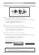
WAVEFORM ← ← ← ← ← ← WAVEFORM WAVEFORM VECTORSCOPE WAVEFORM AUDIO 8CH WAVEFORM VECTORSCOPE AUDIO 8CH WAVEFORM (full screen) VECTORSCOPE (full screen) <Multi>Main View WAVEFORM VECTORSCOPE AUDIO 4CH(12CH) AUDIO PEAK LOG HISTOGRAM USER setting 映像画面 +ウェーブフォーム +ベクトルスコープ +レベルメーター4/12CH +オーディオピークログ +ヒストグラム -36 -48 -42 ユーザー設定 Main View 16 : 9 VECTORSCOPE HISTOGRAM -54 -60 When 16 : 9 AUDIO LEVEL METER -60 ¦¦¦¦¦¦¦¦¦¦¦¦¦¦¦¦¦¦¦¦¦¦¦¦¦¦¦¦¦¦¦¦¦¦¦¦¦¦¦¦¦¦¦¦¦¦¦¦¦¦¦¦¦¦¦¦¦¦¦¦¦¦ ¦¦¦¦¦¦¦¦¦¦¦¦¦¦¦¦¦¦¦¦¦¦¦
HD Monitor HDM-70WV HDM-70WV 調整・設定 User Function Setting ユーザー設定 UTILITY - USER Setting USER Setting UTILITY(測定器機能)のユーザー設定 ユーザー設定 [default setting] デフォルト設定値 Any item can be set to ON or OFF. ユーザー設定画面 任意の機能の表示をそれぞれ設定することができます。 AUDIO AUDIO LEVEL METER [ON] DISPLAY CHANNELS [8] DISP TYPE [OVERLAY] HEADROOM START[-20dB] HEADROOM END [-6dB] オーディオ WAVEFORM AUDIO LEVEL METER VECTORSCOPE VECTORSCOPE ベクトルスコープ VECTORSCOPE [ON] DISP TYPE [OVERLAY] GAIN [ 1.
HD Monitor HDM-70WV Adjustments and Settings User Function Setting 6-3-2 ユーザー設定 Menu of the WAVEFORM for the UTILITY settings ウェーブフォームの設定 WAVEFORM [ON] [default setting] デフォルト設定値 RETURN WAVEFORM [ON] DISP TYPE [OVERLAY] Y OVER LIMIT [95.0%] Y UNDER LIMIT [0.0%] ON OVERLAY 95.0% 0.0% ON or OFF OVERLAY or OVERLAP -7.3 to 109.1 -7.3 to 109.1 Select the WAVEFORM display, ON or OFF. Select the DISPLAY TYPE, OVERLAP or OVERLAY.
HD Monitor HDM-70WV Adjustments and Settings AUDIO Signal Setting 1 AUDIO Function Setting オーディオの設定・調整 オーディオの設定 MENU button On the MENU, select and set the AUDIO functions as follows.
HD Monitor HDM-70WV Adjustments and Settings Audio Signal Setting 音声信号の設定 3 Monitor Audio Signal Selection and Volume Level Adjustment オーディオモニターチャンネルの選択 By pressing the VOLUME / PUSH SELECT knob-button select the monitor audio signal by the monitor speaker or the headphone connected to the jack. The audio volume level of the monitor speaker and the headphone is adjusted by rotating the VOLUME/PUSH SELECT knob or by the MENU setting, VOLUME [from 0 to 40].
HD Monitor HDM-70WV Adjustments and Settings TALLY Signal Setting 1 タリー信号の設定 Make sure that the front and rear TALLY indicators, RED and GREEN, light up properly when the tally signal is input. And make sure that the TALLY OFF/L/H display select switch functions. The brightness of the L position can be selected on the MENU/SAETUP/LOW TALLY BRIGHT, 1 to 8.
HD Monitor HDM-70WV Adjustments and Settings Addition 補足 INFO [1080 i/60] PICTURE MARKER AUDIO [ON] WAVEFORM [ON] VECTORSCOPE [ON] ZEBRA [OFF] SETUP RETURN TIMECODE DISP [OFF] TIMECODE TYPE [LTC] TC TALLY [OFF] LOW TALLY BRIGHT [3] BACKLIGHT [100%] ANALOG CALIBRATE > RESET TO DEFAULT > 1 to 100 CANCEL / 8COLOR CAL NOW CANCEL / CONFIRM CANCEL / RESET NOW CANCEL / CONFIRM Addition for the MENU operation 1 LCD Backlight Adjustment 100 メニューの操作の補足 LCDバックライトの調整 The LCD backlight brightness can be adj
Accessories 付属品 HD Monitor HDM-70WV HDM-70WV/S HDM-70WV HDM-70WV/S 付属品 HDM-70WV<Contents> HDM-70WV HDM-70WV main component Location stand Universal head VF tilt arm stay BNC cable(1.0 m) Power tap cable(1.2 m) AC adaptor and power cable W1/4 male-male screw adaptor W1/4 arm stay screws(5) Combination washers(2) Rubber washers(4+4(spare)) Nylon washers(1+1(spare)) <HDM-70WV セット内容> HDM-70WV本体 ロケ用スタンド ユニバーサルヘッド VF チルトアームステー BNCケーブル(1.0 m) カムタップ電源供給ケーブル(1.
Outside View & Dimensions 外形寸法図 HD Monitor HDM-70WV HDM-70WV 外形寸法図 46.4 35.8 189.5 32.2 147 2-1/4-20 UNC (LEFT, RIGHT) 114.
Specifications 仕様 HD Monitor HDM-70WV LCD Panel HDM-70WV 仕様 LCD パネル Panel type LCDパネルタイプ Panel size パネルサイズ 画面サイズ Size of display area TFT-LCD Active Matrix (TN) 7.0 inches diagonal 152.4(H) x 91.4(V) mm Panel aspect ratio アスペクト比 Picture Resolution 解像度 800(H) x 480(V) x 3(RGB).
HDM-70WV HDM-70WV/S Operating Instructions