
Manual


HDF-700V 各部名称と働き
11
HD View Finder HDF-700V
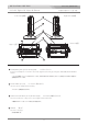
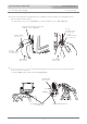
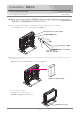
リアパネル
Rear panel
SDI(HD/SD) IN 1 connector (BNC) SDI(HD/SD) IN 1 入力コネクタ
SDI(HD/SD) RET IN connector (BNC) SDI(HD/SD) RET IN リターンビデオ信号 入力コネクタ
SDI(HD/SD) 1 OUT connector (BNC) SDI(HD/SD) 1 OUT 出力コネクタ
ANALOG Y / P
B / PR connectors (BNC) アナログコンポーネント信号 入力コネクタ
RET IN (return control signal input) connector (8-pin) リモート(リターン切替)信号入力コネクタ
Input the HD-SDI or SD-SDI signal from a camcorder, etc.
Outputs the HD-SDI or SD-SDI signal input to the SDI(HD/SD) IN 1 connector.
Connect to the input of a switcher, etc.
Input the return video signal(HD-SDI or SD-SDI) from a switcher, etc.
Input the ANALOG HD Y/P
B/PR component signals from a camcorder, etc.
Connect to the output of a zoom remote controller with the 8-pin cable of the remote controller.
If necessary connect the supplied zoom remote controller extention cable(0.3 m).
Used for switching the input signal, from the SDI IN signal to the RET IN signal.
HD-SDI または SD-SDI 信号をカムコーダー等から入力します。
SD(HD/SD) IN 1 コネクタに入力されたHD-SDI / SD-SDI 信号をスルーで出力します。
スイッチャー等の入力へ接続します。
リターンビデオ信号(SDI)を入力します。スイッチャー等の出力から接続します。
アナログ HD Y/P
B/PR コンポーネント信号をカムコーダー等から入力します。
ズームリモコン(別売オプション, AS-520)を接続します。 必要ならば、付属の延長ケーブルを接続します。
ズームリモコンでリターン切替に使用します。
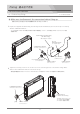
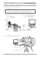
TALLY OFF/L/H display select switch タリー表示切替スイッチ
The brightness of the rear tally indicator(RED only) can be selected as follows.
H : The tally indicator lights up brightly.
L : The tally indicator is dimmed to the lower brightness.
OFF : The tally lamp is prevented from lighting.
リアタリー(レッドのみ)を (OFF(消灯)/L(low:減光)/H(high)) に切替えます。
TALLY 2 connector (BNC) TALLY 2 コネクタ
When this connector is shorted, both the front and rear tally indicators light up to RED.
TALLY 2 コネクタは、入力をショートするとレッドタリーが点灯します。
TALLY 1 connector (BNC) TALLY 1 コネクタ
Input a tally signal to light up the front and the rear tally indicators.
The front tally indicator lights up to RED or GREEN according to the voltage of the tally signal.
(RED : 4-5V, GREEN : 2-4V ). The rear tally indicator lights up only to RED.
タリー信号を入力します。
フロントタリーは、タリー信号の電圧によってRED( 4∼5V ) または GREEN( 2∼4V ) に点灯します。リアタリーはレッドのみです。