
User guide

25
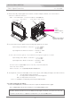
タリー信号の接続
TALLY Signal Connection
1
2
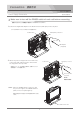
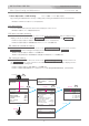
Connect the tally output signal from a camera, a camera adaptor, switcher, etc. to the TALLY 1
connector or TALLY 2 connector.
TALLY 1 コネクタまたはTALLY 1 コネクタにカメラ等のタリー出力を接続します。
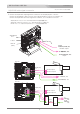
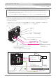
Connection
HD View Finder HDF-700
3
from
camera,
camera adaptor,
switcher, etc.
Display select switch
OFF/L(low)/H(high)
4
In case of using the TC TALLY :
Connect the SDI(HD/SD) 1 or RET IN connector to input the HD/SD-SDI video signal.
TCタリーを使用する場合は、HD/SD-SDI ビデオ信号(エンベデッドTC信号)を接続/入力します。
TC TALLY: When the TC TALLY is set on the MENU, the input signal of the TALLY 1/2 connectors doesnt work.
TC TALLY: TC TALLY がメニューで設定されているときは、TALLY 1/2 コネクタ入力は動作しません。
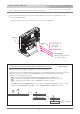
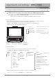
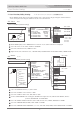
Front TALLY
Rear TALLY
TALLY 1
TALLY 2
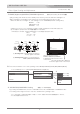
The Front TALLY indicator lights up when the tally input signals are as follows.
The brightness of the Rear TALLY(RED) can be selected by the TALLY OFF/L/H display select swith as follows.
Input voltage of theTALLY 1 connector = 2 - 4 V : GREEN
4 - 5 V : RED
0 - 2 V : OFF
The Rear TALLY indicator lights up only to RED when the tally input signals are as follows.
H : The tally indicator lights up brightly
L : The tally indicator is dimmed to the lower brightness.
OFF : The tally indicator is turned off.
TALLY 2 コネクタは、タリー入力信号が接点のON/OFF の場合使用します。
フロントタリーはタリー入力信号の電圧により, グリーン(2∼4V), レッド(4∼5V)に点灯します。
リアタリーはレッドタリーのみです。
リアタリー(レッド)は切替スイッチで OFF(消灯)/L(low)/H(high) に切替えができます。
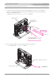
Input signal of the TALLY 2 connector = short(0 V) : RED
open : OFF
Input voltage of the TALLY 1 connector = 4 - 5 V : RED
0 - 2 V : OFF
Input signal of the TALLY 2 connector = short(0 V) : RED
open : OFF
Front TALLY
Rear TALLY