
Instruction Owner manual

8
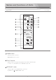
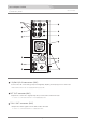
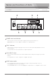
コネクタパネル
Connector panel
Camera Adapter ES−500
AUX (VIDEO OUT/TC IN) connector (BNC)
Outputs the composite video signal connected to the AUX(VIDEO IN) connector of the Base Station
DES−600 or input the time cord signal from a camcorder.
ベースステーションの AUX(VIDEO IN) に入力されたビデオ信号の出力、またはカムコーダーからのタイムコード信号の
入力に使用します。
モニターLVM-89Wへ6ピンケーブル(VC-450)を使って接続します。DC 12V 電源およびタリー信号を出力します。
MONITOR OUT connector (6-pin, female)
Connect to the monitor LVM-89W with the supplied 6-pin cable(VC-450)
The DC 12V power and tally signal are supplied to the LVM-89W.
Outputs the LANC remote control signal to a camcorder. Connect with the supplied LANC control cable.
LANC connector (φ2.5 mini jack)
LANC リモコンのコントロール信号を出力します。 付属の LANCコントロールケーブルを接続します。
ベースステーションDS-560と26ピンマルチケーブルにて接続します。(Sony CCZ-A25/50/100)
CAMERA connector (26-pin, male)
Connect to the Base Station ES−600 with a 26-pin multi-cable (Sony CCZ-A25/50/100).
1
A
B
2
3
4
5
6
7
8
9
10
11
12
13
14
15
16
17
18
19
20
21
22
23
24
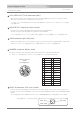
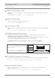
26-pin connector
(male)
pin assignment
1
A
B
2
3
4
5
6
7
8
9
10
11
12
13
14
15
16
17
18
19
20
21
22
23
24
VIDEO OUT
VIDEO SG
MIC OUT
MIC OUT
MIC OUT
REM TX X
GEN IN G
REM VIDEO G
GEN IN X
REM RX X
REM RX Y
+12V
GND
RET V IN
RET V IN G
TALLY IN
Y SG
Y OUT
R-Y OUT
R-Y SG
B-Y OUT
B-Y SG
REM VIDEO X
REM POW
INCOM
REM TX Y
オーディオ信号を入力します。HEADSET コネクタのヘッドセットでMONITOR SELECT スイッチを切り替えてモニターできます。
AUDIO IN connector (XLR 3-pin, female)
Connect an audio input signal from a camcorder. The audio signal can be monitored by the intercom
headset connected to the HEADSET connector selecting the AUDIO IN position of the MONITOR SELECT
switch.
Pin assignment XLR 3-pin,female
1PIN : GND
2PIN : HOT
3PIN : COLD