ES500/600 Operating Instructions Before operating the system, please read this manual thoroughly and retain it for future reference. Volume1, 1st edition Ver.1.
WARNING For the customers in the U.S.A. To reduce the risk of fire or electric shock,do not expose this apparatus to rain or moisture. This equipment has been tested and found to comply with the limits for a Class A digital device, pursuant to Part 15 of the FCC Rules. These limits are designed to provide reasonable protection against harmful interference when the equipment is operated in a commercial environment.
Table of contents Multi-core Studio System NIPROS/V26 NIPROS/V26 目次 Names and Functions of Parts 4 各部名称と働き DS-460 Main panel 4 Connector panel 7 メインパネル コネクタパネル DS-560 Front panel 10 フロントパネル Rear panel 12 リアパネル LVM-89W / Universal Head 15 System Connection 21 Adjustments and Settings 39 System Connection Guide 45 Supplied Accessories 48 Outside View and Dimensions / Specifications 50 接続方法 調節・設定 システム構成例 付属品 外形寸法図・仕様 DS-460 50 DS-560 52 LVM-89W 54 3
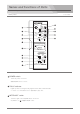
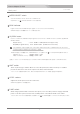
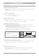
Names and Functions of Parts Camera Adapter ES−500 Main panel メインパネル INTERCOM POWER ON OFF SIDE TONE TALK MIC ON OFF MIN MAX METER LIGHT H.P TALLY ON MIN OFF MAX MONITOR SELECT METER SELECT VU PK INTERCOM AUDIO IN PEAK HYPER LIMITER AUDIO INPUT LIMIT LEVEL MIN ON OFF MAX P-MIC INPUT LEVEL +4dB -20dB -60dB 48V OFF CAMERA ADAPTER (S- 0 POWER switch Turns the power on and off.
Camera Adapter ES−500 Main panel メインパネル METER SELECT switch Selects the Meter mode, VU mode or PEAK mode. VU/PEAKメータ ( ) をVUまたはPEAKメータに切り替えます。 PEAK indicator Lights on when the AUDIO IN input signal is over level even momentarily. AUDIO INの信号レベルが瞬間でもオーバーした時に点灯します。 VU/PEAK meter Used to confirm the AUDIO IN input signal level. VU mode or PEAK mode is selectable by METER SELECT switch.
Camera Adapter ES−500 Main panel メインパネル INPUT LEVEL switch Select the appropriate position according to the input level connected to the AUDIO IN connector on the connector panel. +4dB : When a line-level ( +4 dBm ) signal source is connected. - 20dB : When a line-level ( - 20 dBm ) signal source is connected. - 60dB : When a microphone ( - 60dBm ) is connected. In case of using a codenser microphone, set the P-MIC switch to the 48V position.
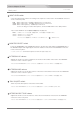
amera Adapter ES−500 Connector panel コネクタパネル RET OUT Y IN Pb IN TALLY OUT MONITOR OUT EXT. AUDIO OUT AUX Pr IN LANC (VIDEO OUT/TC IN) MADE IN JAPAN PUSH ▲HEADSET AUDIO IN ▲ TC OUT ▲ REMOTE VIDEO IN Y IN/Pb IN/Pr IN connectors (BNC) Connect the HD or SD analog component signals(Y, Pb(B-Y), and Pr(R-Y)) from a camcorder.
Camera Adapter ES−500 Connector panel コネクタパネル AUX (VIDEO OUT/TC IN) connector (BNC) Outputs the composite video signal connected to the AUX(VIDEO IN) connector of the Base Station DES−600 or input the time cord signal from a camcorder. ベースステーションの AUX(VIDEO IN) に入力されたビデオ信号の出力、またはカムコーダーからのタイムコード信号の 入力に使用します。 MONITOR OUT connector (6-pin, female) Connect to the monitor LVM-89W with the supplied 6-pin cable(VC-450) The DC 12V power and tally signal are supplied to the LVM-89W.
amera Adapter ES−500 Connector panel コネクタパネル REMOTE connector (8-pin, female) Outputs the remote control signal to a camcorder. Connect with the supplied 8-pin remote cable (RCC-450). RCC-450(付属)を使ってカメラと接続し、リモートコントロール信号を出力します。 VIDEO IN connector (BNC) Input the composite video signal from a camcorder. カムコーダーからコンポジットビデオ信号を入力します。 TC OUT connector (BNC) Outputs the time code signal from the Base Station ES−600. Connect to a camcorder with a BNC cable.
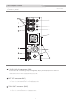
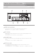
Names and Functions of Parts Base Station ES−600 Front panel フロントパネル ES-600 CABLE 100 EXT LINE (4W I/O) INTERCOM HEADSET 75 50 25 POWER switch and indicator Turns the power on and off. The indicator lights up when the power switch is on. 電源をON/OFFするスイッチです。電源スイッチがONになっている時に点灯します。 TALLY indicator Lights up when receiving the tally signal connected to the TALLY EXT LINE (4W I/O) IN connector on the rear panel.
Base Station ES−600 Front panel フロントパネル INTERCOM HEADSET connector (XLR 4-pin) Connect the supplied intercom headset(DL-400). インカム ヘッドセット(DL-400)を接続します。 In case using the headset with the XLR-4P Male connector, prepare the cable with the XLR 4-pin Female connectors. キャノン4Pオスコネクタのヘッドセットを使用される場合は、 キャノン4Pメス-メスのケーブルをご用意下さい。 1 MIC(G) 2 MIC(H) 1 2 3 4 1 2 3 4 3 H.PHONE(G) 4 H.PHONE(H) INTERCOM HEADSET H.
Base Station ES−600 D Rear panel リアパネル HD/SD COMPONENT OUT Y Pb SDI IN OUT 1 CAMERA VIDEO OUT AUX Pr OUT 2 SDI RET IN OUT 1 AUDIO OUT RET IN VIDEO IN LANC EXT. AUDIO IN TC OUT OUT 2 EXT LINE (2W I/O) EXT LINE (2W I/O) TC IN TALLY EXT LINE (4W I/O) IN OUT AC IN HD/SD COMPONENT OUT Y/Pb/Pr connectors (BNC) Outputs the HD and SD analog component signal, Y, Pb and Pr from the Camera Adaptor ES−500.
Base Station ES−600 Rear panel リアパネル AUX connector (BNC) and VIDEO IN/TC OUT select switch Input the composite video signal from an external vtdeo equipment or outputs the time cord signal from the Camera Adaptor ES−500. Select the VIDEO IN or the TC OUT with the select switch. ビデオコンポジット信号の入力またはDS-460からのタイムコード信号の出力を切替スイッチで切り替えて使用します。 RET IN connector (BNC) Input the composite video return signal from a switcher. ビデオコンポジット リターン信号を入力します。 TC IN connector (BNC) Input a time cord signal.
Base Station ES−600 D Rear panel リアパネル EXT LINE (2W I/O) connectors (XLR 3-pin, female and male) Connect to an external 2-wire intercom line. 2Wインターカムラインに接続します。 Pin assignment XLR 3-pin,female 2PIN : HOT XLR 3-pin,male 2PIN : HOT 1PIN : GND 1PIN : GND 3PIN : COLD 3PIN : COLD TALLY EXT LINE (4W I/O) IN/OUT connectors (HD D-sub 15-pin, female) Used for the tally signal input/output and for the connection to an external 4-wire intercom line.
Names and Functions of Parts HDMI/HD Component Monitor LVM-89W/Universal Head LVM-89W Front Panel HD/Y HD/B-Y HD/R-Y CMP IN CMP OUT TALLY IN MONI IF PEAKING 16:9 MARKER RGB 4:3 DC 12V IN COLOR INPUT MONO Connector Panel (Right Side) Left Side Bottom Panel Screen 8.9 inch liquid crystal display (196(H) 115(V) mm ) 8.9インチ液晶(16:9) The panel might be cracked and have no image when a load is added.
HDMI/HD Component Monitor LVM-89W/Universal Head LVM-89W FRONT TALLY and REAR TALLY display select switch The brightness of the TALLY indicators on the front and rear panels can be selected by the select switches as follows. H : The tally indicator lights up brightly. L : The tally indicator is dimmed to the lower brightness. OFF : The tally indicator is turned off.
HDMI/HD Component Monitor LVM-89W/Universal Head LVM-89W Function buttons PEAKING 16:9 MARKER RGB 4:3 COLOR INPUT MONO INPUT select button : Select the input signal connected to the HD (Y/B-Y/R-Y) component, CMP IN (composite signal input), and HDMI connector. By pressing INPUT button, select the input mode in sequence. The selected mode is displayed on the screen.
HDMI/HD Component Monitor LVM-89W/Universal Head LVM-89W HD/Y, HD/B-Y, HD/R-Y connectors (BNC) Input HD component signals. The input signals are displayed when the input select mode is set to the COMP 1 mode. HD コンポーネント(HD/Y, HD/B-Y, HD/R-Y)信号を入力します。INPUT 切替ボタンをCOMP 1 に切り替えて表示します。 CMP IN connector (BNC) Input a composite video signal. The input signal is displayed when the input select mode is set to the CVBS 1 mode.
HDMI/HD Component Monitor LVM-89W/Universal Head LVM-89W DC 12V IN connector (XLR 4-pin) Connect an external DC 12V power. ( 10∼16V ) DC 12V 電源( 10∼16V, AC アダプタ等)を接続します。 HDMI connector Input a HDMI signal with HDMI cable. The input signal is displayed when the input select mode is set to the HDMI mode. HDMI ケーブルでHDMI信号を入力します。 これは、INPUTボタンで HDMI に切り替えて表示します。 1/4 inch screw hole Fix the supplied universal head.
HDMI/HD Component Monitor LVM-89W/Universal Head Universal Head Monitor lock screw(1/4 inch) モニター固定ネジ Used to fix the monitor. モニターを固定します。 Angle adjustment knob 角度調節ノブ Used to adjust the monitor position to any angle so that the display can be watch well. モニターの画面を見やすい角度に調節し、固定します。 Slide-shoe lock knob スライドシュー固定ノブ Used to fix the Slide Shoe to a camera accessory shoe. モニターのスライドシューをカメラのアクセサリーシューに固定します。 Slide-shoe スライドシュー Slide into a camera accessory shoe.
System Connection Multi-core Studio System NIPROS/V26 Make sure to turn off the POWER switch of each unit before connecting. 接続する前に必ず各機器の電源スイッチを OFFにしてください。 Mount on the tripod 1 三脚への取り付け Fix the Camera Adaptor DS-460 to the V-shoe mount of the camcorder. カムコーダーの VシューマウントにDS-460 を固定します。 RET OUT 2 MONITOR OUT Mount the camcorder and DS-460 on a tripod.
Multi-core Studio System NIPROS/V26 Fix the monitor LVM-89W 1 LVM-89Wモニターの取り付け Fix the supplied universal head to the screw hole on the bottom surface of LVM-89W with the Monitor Lock Screw. LVM-89W底部の1/4インチ固定ネジ穴にユニバーサルヘッドをモニター固定ネジで固定します。 Bottom Panel Monitor Lock Screw Universal head 2 Slide the universal head with LVM-89W into the accessory shoe of the camcorder untill the slide-shoe stops in place. Tighten the Slide-Shoe Lock Knob to fix the universal head with the accessory shoe.
Multi-core Studio System NIPROS/V26 NIPROS/V26 接続方法 LVM-89W connection LVM-89Wの接続方法 Monitoring the video signal 1 Connect an external DC 12V power supply with a XLR 4-pin cable. Or connect the MONI IF connector to the MONITOR OUT connector of the Camera Adaptor with the supplied 6-pin cable(VC-450). DC 12V IN コネクタへ DC 12V 電源をキャノン4ピンケーブルで接続します。 またはMONI IFコネクタへカメラアダプタから付属の6ピンケーブル(VC-450)を接続します。 2 Connect the input signal to the appropriate connector according to the video signal from a camcorder.
Multi-core Studio System NIPROS/V26 NIPROS/V26 接続方法 26-pin multi-cable connection 1 26ピンカメラケーブルの接続 Connect both the 26-pin CAMERA connectors of the Camera Adaptor and the Base Statioin with a 26-pin multi-cable. 26 ピンケーブルでカメラアダプタとベースステーションとを接続します。 DS-460 RET OUT Y IN Pb IN TALLY OUT MONITOR OUT EXT.
Multi-core Studio System NIPROS/V26 NIPROS/V26 接続方法 HD/SD component video signals connection 1 HD/SDコンポーネントビデオ信号の接続 Connect the HD/SD component video output signals from a camcorder to the Y IN/Pb IN/Pr IN connectors of DS-460 with BNC cables. カムコーダーからの HD/SD コンポーネント信号出力は、Y IN/ Pb IN/Pr IN コネクタへ BNC ケーブルで接続します。 HD/SD component video signals RET OUT Y IN from camcorder Pb IN TALLY OUT Y IN MONITOR OUT Pb IN EXT.
Multi-core Studio System NIPROS/V26 Composite video signal connection 1 コンポジットビデオ信号の接続 Connect the composite video output signal from a camcorder to the VIDEO IN connector with a BNC cable. カムコーダーのコンポジットビデオ信号出力は、VIDEO IN コネクタへ BNCケーブルで接続します。 DS-460 RET OUT Y IN Pb IN TALLY OUT MONITOR OUT EXT.
Multi-core Studio System NIPROS/V26 NIPROS/V26 接続方法 Return composite video signal connection 1 リターンコンポジットビデオ信号の接続 Connect the RET OUT connector to a monitor, etc. with a BNC cable. リターンコンポジットビデオ信号の出力は、RET OUT コネクタからモニター等へ BNC ケーブルで接続します。 DS-460 RET OUT (BNC) RET OUT Y IN Pb IN TALLY OUT Pr IN AUX return composite video signal to monitor, etc. MONITOR OUT EXT.
Multi-core Studio System NIPROS/V26 リターンコンポジットビデオ信号/ LVM-89Wの接続 Return composite video signal connection with LVM-89W In case of using the supplied monitor LVM-89W to display the retun signal : 1 Connect the RET OUT connector of the camera adaptor DS-460 and the CMP IN (composite signal input) connector of the monitor LVM-89W with a BNC cable.
Multi-core Studio System NIPROS/V26 NIPROS/S26 接続方法 AUX composite video signal connection 1 AUXコンポジットビデオ信号の接続 Connect the AUX (VIDEO OUT/TC IN) connector to a prompter, etc. with a BNC cable. (NOTE : Set the VIDEO IN/TC OUT select switch of the base station DS-560 to the VIDEO IN position.) ビデオコンポジット信号を出力する場合は、AUX (VIDEO OUT) コネクタへ BNC ケーブルで接続します。 ( 注 : ベースステーション DS-560 の VIDEO IN/TC OUT 切替スイッチを VIDEO IN にセットします。) DS-460 RET OUT Y IN Pb IN EXT.
Multi-core Studio System NIPROS/V26 Time code signal connection TC信号の接続 Time code signal to a camcorder : 1 Connect the TC OUT connector of DS-460 to a camcorder with a BNC cable. TC 信号を出力する場合は、DS-460 の TC OUT コネクタからカムコーダーへ BNC ケーブルで接続します。 2 Connect the time code output signal from a time code signal generator to the TC IN connector of DS-560 with a BNC cable. TC IN コネクタへ TC 信号発生器から BNC ケーブルで接続します。 RET OUT Y IN Pb IN TC signal to camcorder MONITOR OUT TALLY OUT EXT.
Multi-core Studio System NIPROS/V26 HD/SD SDI video signal connection HD/SD SDIビデオ信号の接続 1 HD/SD SDI signal : Connect the HD/SD SDI output signal from a camcorder to the SDI IN connector of DS-560 with a BNC cable. And connect the SDI OUT1/2 connectors to a switcher, a monitor, a VTR, etc. with a BNC cable.
Multi-core Studio System NIPROS/V26 NIPROS/V26 接続方法 AUDIO signal connection オーディオ信号の接続 1 In case of the audio signal input : Connect the audio output signal from a camcorder to the AUDIO IN connector with a XLR 3-pin cable. オーディオ 信号を入力する場合は、AUDIO IN コネクタ ( キャノン 3 ピン)へ接続します。 RET OUT Y IN ON audio signal INTERCOM POWER OFF Pb IN TALLY OUT SIDE TONE TALK ON OFF MIC METER LIGHT TALLY ON H.
Multi-core Studio System NIPROS/V26 NIPROS/V26 接続方法 INTERCOM HEADSET connection 1 インターカムヘッドセットの接続 DS-460 : Connect the supplied headset DL-400 to the INTERCOM HEADSET connector(XLR 4-pin, male) on the connector panel. 付属のヘッドセット DL-400 を INTERCOM HEADSET コネクタ ( キャノン 4 ピン , オス ) へ接続します。 RET OUT Y IN Pb IN TALLY OUT MONITOR OUT EXT.
Multi-core Studio System NIPROS/V26 INTERCOM 2W line/4W line connection インターカムの接続 1 INTERCOM 2W line : Connect the EXT LINE (2W I/O) connectors (XLR 3-pin, female and male) to an external intercom 2W line with a XLR 3-pin cable. インターカム 2W ラインに接続する場合は、EXT LINE (2W I/O) コネクタにキャノン 3P ケーブルで接続します。 HD/SD COMPONENT OUT Y Pb SDI IN OUT 1 VIDEO OUT AUX Pr OUT 2 CAMERA SDI RET IN OUT 1 AUDIO OUT RET IN VIDEO IN LANC TC OUT OUT 2 EXT.
Multi-core Studio System NIPROS/V26 NIPROS/V26 接続方法 TALLY signal connection 1 タリー信号の接続 Connect the TALLY OUT connector of the camera adaptor DS-460 to a monitor with a BNC cable. タリー信号を出力する場合は、DS-460 の TALLY OUT コネクタからモニターへ BNC ケーブルで接続します。 DS-460 RET OUT Y IN Pb IN TALLY OUT TALLY OUT MONITOR OUT to monitor EXT. AUDIO OUT AUX Pr IN LANC TALLY signal (VIDEO OUT/TC IN) MADE IN JAPAN PUSH ▲HEADSET AUDIO IN ▲ TC OUT ▲ REMOTE VIDEO IN TALLY signal from switcher, etc.
Multi-core Studio System NIPROS/V26 NIPROS/V26 接続方法 REMOTE controller connection リモコンの接続 In case of using a 8-pin remote controller (Sony RM-B750,B150, etc.) : 1 Connect a 8-pin remote controller (Sony RM-B150, B750, etc.) to the REMOTE connector of DS-560(rear panel) by the supplied cable with a remote controller.
Multi-core Studio System NIPROS/V26 NIPROS/S26 接続方法 POWER supply connection 1 電源の接続 DC power supply to DS-460 : The DC power to DS-460 is supplied from the base station DS-560 via the 26-pin multi-cable. Connect both the CAMERA connectors of DS-460 and DS-560 with the 26-pin multi cable and connect the AC IN connector of the base station DS-560.
Multi-core Studio System NIPROS/V26 NIPROS/V26 接続方法 POWER supply connection 2 DC電源の接続 DC power supply to a camcorder : The DC 12V power is supplied to the camcorder from the V-shoe battery adaptor. カムコーダーへ、DC 12V 電源は V シューバッテリーアダプターから供給されています。 RET OUT Y IN Pb IN MONITOR OUT TALLY OUT EXT.
Adjustments and Settings Multi-core Studio System NIPROS/V26 Turn on the power switches of ES-500, ES-600, LVM-89W and Camcorder Make sure the volume of each unit is set to the minimum position before starting adjustment. Never turn up the volumes suddenly to prevent hearing impairment.
Multi-core Studio System NIPROS/V26 NIPROS/V26 調整と設定 Adjustments and Settings for DS-460 DS-460 調整と設定 Power switch POWER ON TALLY indicator LED RET OUT Y IN INTERCOM OFF Pb IN TALLY OUT SIDE TONE TALK ON OFF MIC MIN MAX METER LIGHT H.P TALLY ON MONITOR OUT EXT.
Adjustments and Settings Multi-core Studio System NIPROS/V26 Adjustments and Settings for ES600 Power switch TALLY indicator ES-600 CABLE 100 EXT LINE (4W I/O) INTERCOM HEADSET 75 50 25 1 SIDE TONE SIDE TONE 3 IN OUT 1 CABLE select switch setting 2 MIC H.P HEADSET ケーブル切替スイッチの設定 Set the CABLE select switch to the appropriate position according to the length of the 26-pin multi-cable connected to the CABLE connector.
Multi-core Studio System NIPROS/V26 Adjustments and settings for ES- 600 3 INTERCOM EXT LINE (4W I/O) IN/OUT/SIDE TONE volume adjustment インターカム4W ライン入出力レベルの調整 Connect an external 4-wire intercom line to the TALLY EXT LINE (4W I/O) connector. 外部インターカムライン(4W)を EXT LINE (2W I/O)コネクタに接続します。 Put on the headset DL-400 ヘッドセットDL-400を装着します。 While listening to your own voice and the other operators voice, turn up the EXT LINE (4W I/O) IN andOUT volumes gradually so that both the voices can be heard clearly. H.P.
Adjustments and Settings Multi-core Studio System NIPROS/V26 Settings for LVM-89W LVM-89W 設定 1 Input Signal Selection Select the input mode by pressing the INPUT select button on the front panel according to the input signal connected to the input connectors.
Multi-core Studio System NIPROS/V26 Settings for LVM-89W LVM-89W 設定 3 Menu / Entry Setting By pressing the the MENU button select the menu and by pressing - / + buttons, select each setting value according to the menu and the value displayed on the screen in sequence.
System Connection Guide Multi-core Studio System NIPROS/V26 LVM-89W HD Component recording system Supplied Accessories CMP IN 付属品リスト MONITOR LVM-89W 1 UNIVERSAL HEAD 1 HEADSET DL-400 2 6-PIN CABLE VC-450 1 PEAKING 16:9 MARKER RGB 4:3 MONO MONI IF BNC CABLE 1m MONITOR OUT 6P CABLE VC-450 RET OUT Y IN Pb IN Pr IN Y IN Pb IN BNC CABLE 38cm 3 BNC CABLE 1m 1 D-SUB 15PIN-D-SUB 15PIN CABLE 1 D-SUB 15PIN-CUT CABLE 1 UNIVERSAL HEAD Camera Adaptor DS-460 HEADSET DL-400 COLOR INPUT REMOTE CABLE
System Connection Guide Multi-core Studio System NIPROS/V26 NIPROS/V26 システム構成例 LVM-89W HD-SDI recording system HD MONITOR(optional) Supplied Accessories CMP IN SDI IN MONI IF DC IN 付属品リスト MONITOR LVM-89W 1 UNIVERSAL HEAD 1 HEADSET DL-400 2 PEAKING 16:9 MARKER RGB 4:3 6-PIN CABLE VC-450 1 UNIVERSAL HEAD BNC CABLE 38cm 3 BNC CABLE 1m 1 D-SUB 15PIN-CUT CABLE 1 HEADSET DL-400 LANC CONTROL CABLE 1 AC CABLE 1 MONO BNC CABLE 1m D-SUB 15PIN-D-SUB 15PIN CABLE 1 REMOTE CABLE RCC-450 1 COLOR INP
Multi-Camera System Connection Guide Multi-core Studio System NIPROS/V26 NIPROS/V26 システム構成例 HD-SDI recording system HD-SDI Monitor Monitor LVM-89W ●Camera 1 CMP IN HEADSET DL-400 HEADSET DL-400 SDI OUT HEADSET (front) HD/SD COMPONENT OUT Y Pb SDI IN SDI IN(BNC) VIDEO OUT AUX OUT 1 OUT 2 RET IN VIDEO IN LANC Pr TC OUT OUT 2 SDI RET IN OUT 1 EXT.
Supplied Accessories Multi-core Studio System NIPROS/V26 NIPROS/V26 付属品 Description Model name Quantity Monitor LVM-89W 1 Universal Head 1 Headset DL-400 2 6-pin Cable VC-450 1 BNC Cable 41 cm 3 BNC Cable 1 m 1 D-sub 15-pin - D-sub 15-pin Cable 1 D-sub 15-pin - Cut Cable 1 RCC-450 Remote Cable 1 LANC Control Cable 1 AC Cable 1 Operating Instructions(CDROM) 1 48
TALK INTERCOM PEAK INTERCOM AUDIO IN 50 P-MIC LIMIT 外形寸法図(単位:ミリ) 70 DS-460 +4dB -20dB -60dB INPUT LEVEL MAX MIN LEVEL AUDIO INPUT CAMERA ADAPTER 48V OFF ON OFF MONITOR SELECT MAX MIN H.P MAX MIN MIC SIDE TONE HYPER LIMITER VU PK METER SELECT OFF TALLY ON METER LIGHT ON OFF OFF POWER ON 122 ▲HEADSET AUDIO IN MADE IN JAPAN REMOTE VIDEO IN TC OUT AUX Pr IN PUSH LANC EXT.
Specifications Camera Adapter ES−500 出力 Output Return RET OUT :1 BNC x1: 1Vp-p, 75Ω, Anaglog composite or HD-Y ※1 VIDEO OUT :1 BNC x1: 1Vp-p, 75Ω, Anaglog composite Monitor I/F MONITOR OUT :1 Mini 6-pin(female) x1: DC 16V 1A , TALLY signal Tally TALLY OUT :1 BNC x1 Time Code TC OUT :1 BNC x1 DC V-mount :1 DC 16V (maximum 4.
Outside View and Dimensions 320 Base Station Des−600 215 71 ES600 CABLE EXT LINE (4W I/O) 100 HEADSET INTERCOM 75 50 25 HD/SD COMPONENT OUT Y Pb SDI IN OUT 1 CAMERA VIDEO OUT AUX Pr OUT 2 SDI RET IN OUT 1 AUDIO OUT RET IN VIDEO IN LANC TC OUT OUT 2 EXT.
Specifications Base Station ES−600 出力 Output HD/SD - SDI SDI OUT :1 BNC x2: 1Vp-p, 75Ω, Audio, T/C embedded SDI RET OUT :1 BNC x2: 1Vp-p, 75Ω, HD component HD/SD COMPONENT OUT :1 Video VIDEO OUT :1 BNC x1: 1Vp-p, 75Ω, Anaglog composite or HD-Y ※1 Audio AUDIO OUT :1 XLR 3-pin(male) x1 TC OUT :1 BNC x1 Time Code AUX* BNC x3: 1Vp-p, 75Ω, Y/Pb/Pr, auto detecting (HD/SD) 入力 Input HD/SD - SDI Video Video AUX* Time Code SDI IN :1 BNC x1: 1Vp-p, 75Ω, Audio, TC embedded SDI RET IN :1 BNC x
Outside View and Dimensions HDMI/HD Component Monitor LVM-89W/Universal Head 35mm 217mm HD/Y HD/B-Y 149mm HD/R-Y CMP IN CMP OUT TALLY IN MONI IF PEAKING 16:9 MARKER RGB COLOR INPUT DC 12V IN MONO 7mm 52mm 4:3 Outside dimension (unit: mm) 外形寸法図(単位:ミリ) 54
Specifications HDMI/HD Component Monitor LVM-89W/Universal Head LVM-89W Size 画面サイズ 8.9 inch-type 8.
ES-500 / ES-600 NIPROS/V26 Operating Instructions