MN-800-TF REVERSE OSMOSIS TREATMENT SYSTEM OWNERS MANUAL Nimbus Water Systems 41840 McAlby Court, Suite A Murrieta, CA 92562-7036 800-451-9343
THE NIMBUS MN-800 TF REVERSE OSMOSIS TREATMENT SYSTEM TABLE OF CONTENTS §1.0 MN-800 TF SYSTEM SPECIFICATIONS .......................................................................... 3 §2.0 SYSTEM COMPONENTS (See Figure 1).......................................................................... 3 §3.0 PRE-INSTALLATION PROCEDURES............................................................................... 7 §4.1 LOCATION ....................................................................................
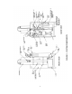
THE NIMBUS MN-800 TF REVERSE OSMOSIS TREATMENT SYSTEM The Nimbus MN-800 TF is the perfect system for a wide variety of applications. Features include stainless steel pressure vessels, frame and concentrate recirculation valve. There are pressure gauges on the pre-filter outlet, post-filter inlet and the high pressure outlet of the desalinator array. The MN-800 TF is also equipped with a 20" 10µ (micron) carbon cartridge pre-filter and postfilter.
CONCENTRATE RECIRCULATION VALVE: A needle valve that controls the amount of concentrate from the desalinator array to be recirculated back into the feed stream. This feature allows for higher recovery rates. Additionally, adjustment of this valve regulates the pump discharge pressure. FLOW CONTROL: A fixed orifice that controls the amount of water flowing across the membrane to drain.
ANCILLARY EQUIPMENT: The following items are also covered in this manual to form a complete water treatment system. PRESSURE TANK: The tank provides storage for approximately 34 gallons of treated water at a pressure of 40 to 60 psi. REMOTE BY-PASS PANEL: This panel monitors treated water TDS and storage tank pressure. It includes a valve for switching to delivery of city water to the food service machines in the event of an RO system failure.
§3.0 PRE-INSTALLATION PROCEDURES PLEASE READ CAREFULLY. FAILURE TO FOLLOW THESE PROCEDURES CAN RESULT IN DAMAGE TO YOUR SYSTEM AND VOID YOUR WARRANTY. §3.1 PACKAGING Upon delivery, inspect packaging for damage and report it to your carrier at that time. After unpacking the system, inspect it carefully for signs of damage. All damage claims should be made to the delivery carrier. §3.2 OPERATING LIMITATIONS Nimbus MN-800 TF units are to be used on potable water only.
§4.0 INSTALLATION PLEASE READ CAREFULLY BEFORE BEGINNING INSTALLATION. FAILURE TO FOLLOW THESE PROCEDURES CAN RESULT IN DAMAGE TO YOUR SYSTEM AND VOID YOUR WARRANTY. §4.1 LOCATION It is recommended that systems be located where they are protected from harsh environments such as rain, snow and extreme temperatures (both hot and cold). MN-800 TF units can be located just about anywhere there is a water and electrical supply.
piece of black 5/8” tubing from the valve up to the 5/8” compression fitting at the back right side of the RO system manifold. §4.2.2 BY-PASS PANEL PREPARATION AND INSTALLATION: The by-pass panel is to be located convenient to the RO where the TDS monitor is visible and the valve can be operated without difficulty. The standard fittings provided are ½” MPT x 5/8” compression to be installed directly in the 3 ½” FPT ports at the bottom of the panel.
§5.0 SYSTEM FLUSH AND PERFORMANCE VERIFICATION Although MN-800-TF systems are fully tested at the factory prior to shipping, it is recommended to flush and verify your system's performance on-site. §5.1 SYSTEM FLUSH AND OPERATION New membranes have a preservative on them that needs to be flushed before use. • Open the fast flush valve and all usage outlets to allow product to run to drain. • Fully open the concentrate recirculation valve by turning the knob counterclockwise.
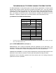
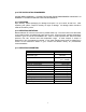
• As a final check turn on the city water valve to the By-Pass Panel and check the plumbing for leaks. §5.2 PERFORMANCE VERIFICATION Factory test data is supplied with the system. To ensure optimum performance, on-site data should be taken and compared to the factory test data. This data should be taken after the system has been flushed for one hour. Some deviations may be seen due to differences in feed water TDS and temperature between the site and factory.
gauge reads about 60 psi (4.1 bar). Now, by opening the tank inlet valve the tank pressure should begin to drop and the system should turn on when the pressure drops below about 40 psi (2.8 bar). If the system fails to shut off at 60 psi (4.1 bar), watch the gauge and be sure that it does not rise above 80 psi (5.5 bar). If it reaches 80 psi (5.5 bar), unplug the system. Refer to §7.1.2 for TANK PRESSURE SWITCH ADJUSTMENT. §6.
psi (1.4 bar). • Before servicing, always disconnect power to the unit to avoid shock. • To adjust, remove cover and refer to the diagram inside the cover. • Turn adjustment nut #1 counterclockwise to decrease cut-out pressure and clockwise to increase cut-out pressure. Under normal circumstances it is not necessary to adjust this switch setting. • Replace cover and restore power to unit. ALWAYS BE SURE TO CHECK THE CUT-OUT OPERATION AFTER ADJUSTMENT AS OUTLINED IN §5.2.4 LOW PRESSURE SWITCH TEST.
• Tag and disconnect the three tubing connections on the desalinator namely the feed, concentrate and product. • Unsnap the desalinator retainers and pull desalinator(s) out. • Remove retaining clips from ends of desalinator by tapping the open ends of the clips with a plastic or rawhide mallet until they are through the slots in the pressure vessel. Pull clips completely out of pressure vessel. • Remove end plugs by gently pulling on the fittings.
• Since the membrane is new it will need to be flushed and tested. Follow procedures outlined in §5.0 SYSTEM FLUSH AND PERFORMANCE VERIFICATION. §7.4 PRE FILTER CARBON CARTRIDGE REPLACEMENT • Before servicing, always disconnect power to the unit to avoid shock. • Close feed water and tank valves. • Activate the switch on the side of the gray box in the back of the unit just enough to relieve any pressure in the filter. • Remove pre-filter sump by turning clockwise (as viewed from the top).
• Inspect sump for cracks. Replace as necessary. • Lubricate O-ring with an appropriate petroleum or silicone-based lubricant. Install O-ring into its seat in sump. • Install new carbon cartridge with the white rubber ring up. • Replace sump by screwing it onto cap in a counter-clockwise direction (as viewed from top). A wrench should not be needed. Hand tightened is sufficient. • Restore water and power; check for leaks. ● Note: New carbon cartridges need to be flushed after being installed.
§8.
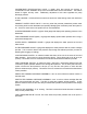
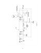
§9.0 ATTACHMENTS §9.1 REMOTE BYPASS SYSTEM INSTRUCTIONS Indication – When water is required even though RO product water of the desired quality is not available. This unit allows for the supply of feed water to supplement the RO water requirement. Installation – See the diagram below for plumbing the system. As a minimum, use tubing of at least the RO product water outlet connection size.
§9.2 TDS MONITOR INSTRUCTIONS Model TDS-2B TDS Monitor Part # 100860 The Nimbus TDS-2B TDS Monitor is designed to operate within the Remote Bypass Unit of the Nimbus MN system. It is installed inside the upper left corner of the Bypass Unit frame and is connected to a tee fitting installed in the product water output line. The Monitor is powered by a 9V battery accessible via a sliding cover at the rear of the case.
§9.3 WARRANTY Nimbus Water Systems Limited One Year Warranty Commercial and Industrial Systems The Nimbus Water Systems (Nimbus) Limited Warranty extends to the original purchaser of the system. This warranty covers all parts and factory labor needed to repair any Nimbus-supplied item that proves to be defective material, workmanship or factory preparation. The above-mentioned warranty applies for the first full calendar year from the date of purchase.