www.nilfisk-alto.
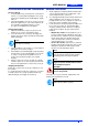
B 2 3 9 D 4 E 5 9 9 8 7 9 1 6 S310027 F S310028 G S310025 C 18 5 25 S310029 3 H 27 19 5 20 23 14 17 8 2 16 I 4 7 24 6 12 5 S310081 J 10 S310030 26 9 15 22 13 S310032 K 8 21 11 S310080 S310082 S310034
USER MANUAL ENGLISH INTRODUCTION ................................................................................................................................... 2 MANUAL PURPOSE AND CONTENTS ........................................................................................................... 2 TARGET ........................................................................................................................................................... 2 HOW TO KEEP THIS MANUAL ................
ENGLISH USER MANUAL INTRODUCTION OTHER REFERENCE MANUALS – MANUAL PURPOSE AND CONTENTS The purpose of this Manual is to provide the operator with all necessary information to use the machine properly in a safe and autonomous way. It contains information about technical characteristics, operation, machine storage, maintenance, spare parts and safety conditions.
USER MANUAL ENGLISH SYMBOLS DANGER! It indicates a dangerous situation with risk of death for the Operator. WARNING! – WARNING! It indicates a potential risk of injury for people. CAUTION! It indicates a caution or a remark related to important or useful functions. Pay attention to the paragraphs marked by this symbol. NOTE Consult the User manual before performing any procedure. GENERAL INSTRUCTIONS Specific warnings and cautions to inform about potential damages to people and machine are shown below.
ENGLISH – USER MANUAL In case of part replacement, order ORIGINAL spare parts from an authorised Dealer or Retailer. To ensure the proper and safe operation of the machine, have the scheduled maintenance, detailed in the related chapter of this Manual, performed by the authorised personnel or an authorised Service Center. The machine must be disposed of properly, because of the presence of toxic-harmful materials (batteries, oils, etc.
USER MANUAL Under-hood compartment (See Fig. U) 1. Hood (open position) 2. Batteries 3. Battery connector 4. Electronic battery charger (optional) 5. Battery charger electrical cable 6. Main fuse 7. Side broom motor fuse 8. (Lead) battery caps 9. Lead (WET) or gel (GEL) battery selector switch located on the optional electronic battery charger 10. Battery assembly diagram 11. Charged battery warning light 12. Main broom belt 13. Drive belt 14. Main broom drive pulley 15. Rear wheels drive pulley 16. Fan 17.
ENGLISH USER MANUAL USE c) WARNING! On some points of the machine there are some adhesives indicating: – DANGER – WARNING – CAUTION – NOTE Without battery 1. Buy an appropriate battery (See Technical Characteristics paragraph and the diagram 10, Fig. U). For the battery choice and installation, apply to qualified battery retailers. 2. Install the battery. 3. Proceed with machine and battery charger (if installed) setting according to the chosen battery type.
USER MANUAL STARTING AND STOPPING THE MACHINE MACHINE OPERATION At every start-up 1. Insert the ignition key (2, Fig. B) in the control panel; turn it to “I” position [without pulling the lever (4, Fig. C)], then check that the green warning light (5, Fig. B) turns on. 2. If the warning light becomes green or red (3 or 4, Fig. B) take the ignition key to “0” position and take it out. Proceed with recharging the batteries (see the procedure in the Maintenance paragraph). 1. Starting the machine 1.
ENGLISH USER MANUAL HOPPER EMPTYING 1. 2. 3. Release the lever to stop the machine. Turn the ignition key (2, Fig. B) to “0” position. Disengage the hook (18, Fig. C) by pulling its inferior end. By means of the handle (19, Fig. C) pull out the hopper (17) and empty it. Take back the hopper to its normal position and engage the hook (18). The machine is ready to start working again. 4. 5. 6. AFTER USING THE MACHINE After working, before leaving the machine: 1.
USER MANUAL ENGLISH SCHEDULED MAINTENANCE TABLE Operation On delivery Battery fluid level check Every 10 hours Every 50 hours Every 100 hours Every 200 hours Every 400 hours (1) Driving belt visual inspection: traction, main broom (*) Skirt height and operation check Side and main broom height check Dust filter cleaning and integrity check Electrical filter-shaker (optional) operation check (1) (*) Nut and screw tightening check Driving belt tensioner adjustment (*) (*) Driving belt replace
ENGLISH USER MANUAL MAIN BROOM REPLACEMENT SIDE BROOM HEIGHT ADJUSTMENT NOTE Brooms of various hardness are available. This procedure is applicable to all types of brooms. NOTE Brooms of various hardness are available. This procedure is applicable to all types of brooms. CAUTION! It is advisable to use protective gloves when replacing the main or side brooms because there can be cutting debris between the bristles. 1. 2. 3. 4. 5. 6. 7. 8. 9. 10. 11. 12. 13. 14.
USER MANUAL DUST FILTER CLEANING AND INTEGRITY CHECK NOTE Besides the standard paper filter, polyester filters are also available. The following procedure is applicable to each type of filter. 1. Drive the machine on a level ground and activate the pedal brake (26, Fig. C) (if present). 2. Turn the ignition key (2, Fig. B) to “0” position. 3. Disengage the retainer (18, Fig. C). 4. Remove the hopper (17) by using the handle (19, Fig. C). 5. Turn the handle (1, Fig.
ENGLISH USER MANUAL If necessary, adjust the skirt height by using the slots (3, Fig. R). 10. Activate the front skirt lifting lever (27, Fig. C) and check that the front flap (1, Fig. Q) rotates upward of 90° (as shown in figure); release the lever and check that the skirt returns to the initial position and does not stay in an intermediate one. If necessary, for the front skirt control cable adjustment or replacement, refer to the Service Manual. 11.
USER MANUAL SAFETY FUNCTIONS SCRAPPING HOOD SAFETY SWITCH It is activated when the machine hood is raised. It stops all functions. In case of machine start even when the hood is open, contact an authorized Service Center or Retailer. TROUBLESHOOTING TROUBLE REMEDY Check the battery connector (3, Fig. U) for proper connection. When the key is to “I” position the machine does not start. ENGLISH Have the machine scrapped by a qualified scrapper.
ENGLISH USER MANUAL EC CERTIFICATE OF CONFORMITY (& GHFODUDWLRQ RI FRQIRUPLW\ $OWR 'HXWVFKODQG *PE+ *XLGR 2EHUGRUIHU 6WUDH ' %HOOHQEHUJ 3URGXFW 6ZHHSHU 0RGHO )/2257(& % 'HVFULSWLRQ 9 7KH GHVLJQ RI WKH DSSOLDQFH FRUUHVSRQGV WR WKH IROORZLQJ SHUWLQHQW UHJXODWLRQV (& 0DFKLQH 'LUHFWLYH (& (& /RZ 9ROWDJH 'LUHFWLYH ((& (& (0& 'LUHFWLYH ((& $SSOLHG KDUPRQL]HG VWDQGDUGV (1 (1 (1 (1 (1 (1 (1 $SSOLHG QDWLRQDO VW
L M U S310035 N S310036 P O S310083 S310037 Q S310084 R 4 3 1 S310085 S 3 2 S310040 T S310041 S310042 S310087
V CN2 SW2 Nilfisk-ALTO HEADQUARTER SW1 WH BN OG RD DENMARK Nilfisk-Advance Group Sognevej 25 2605 Brøndby Denmark Tel: (+45) 43 23 81 00 OG BU SUBSIDIARIES CN1 RD F1 RD ES1 RD + V1 GY C3 - C1 GY M2 - EB1 C2 + BATTERIES 12V CN1 Gel Pb AUSTRIA ALTO Österreich GmbH Nilfisk-Advance AG Metzgerstrasse 68 5101 Bergheim/Salzburg Austria Tel : (+43) 662 456 400 11 Fax: (+43) 662 456 400 34 E-mail: verkauf@nilfisk-alto.at www.nilfisk-alto.