User's Manual CLE4.0 QUAD COMPRESSOR/LIMITER R LTO www.altoproaudio.com Version 2.0 Dec.
the recommended fuse type as indicated in this manual. Do not short-circuit the fuse holder. Before replacing the fuse, make sure that the product is OFF and disconnected from the AC outlet. SAFETY RELATED SYMBOLS CAUTION RISK OF ELECTRIC SHOCK DO NOT OPEN Protective Ground This symbol, wherever used, alerts you to the presence of un-insulated and dangerous voltages within the product enclosure. These are voltages that may be sufficient to constitute the risk of electric shock or death.
PREFACE Dear Customer: Thanks for choosing LTO CLE 4.0 Quad/Compressor/Limter and thanks for choosing one of the results of AUDIO TEAM job and researches. LTO For our LTO AUDIO TEAM, music and sound are more then a job...are first of all passion and let us say... our obsession! We have been designing professional audio products for a long time in cooperation with some of the major brands in the world in the audio field.
TABLE OF CONTENTS 1. INTRODUCTION......................................................................................................................................4 2. THE CONCEPT BEHIND........................................................................................................................4 2.1 Some technical stuff 2.2 Voltage Controlled Amplifier (VCA) 2.3 Inputs 3. CONTROL ELEMENTS .........................................................................................................
1. INTRODUCTION You are now the Owner of an LTO CLE 4.0 Quad Compressor/Limiter. The CLE 4.0 is a very powerful dynamic processor. We have included in it several innovative circuit designs that make the CLE 4.
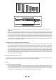
Chart. 1 The dynamic range capabilities of various devices Clipping Aera Noise Aera Clipping Signal heavily distrorted Low level signal drowned out by noise Chart. 2 The interactive relationship between the operating level and the headroom So the operating level must be as high as possible but not high enough to generate distortion. Tricky uh? There is a very easy way to obtain this. With the volume knob in hand you increase the volume during low passages and decrease the volume during loud passages.
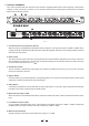
3. CONTROL ELEMENTS Your CLE 4.0 presents with four channels. Each channel is equipped with the same control elements: 3 push-button switches, 4 rotary controls and 17 LEDs. You can operate in stereo mode via pressing the Couple switch. The details please refer to following content. 8 7 GAIN REDUCTION(dB) 30 25 20 15 10 6 3 INPUT / OUTPUT LEVEL(dB) 1 24 18 12 0 6 2.5 10 10 6 0 12 GAIN REDUCTION(dB) 18 30 LIM 12 CH1 25 20 15 10 6 3 INPUT / OUTPUT LEVEL(dB) 1 24 18 12 2.
9. Threshold Control for Limiter The threshold Level for the Limiter will be adjusted by this control 10. Limiter LED When the Limiter is active, this LED will flash up. 11. Couple Switch When pressing this button Channel 1 and 3 will operate in stereo mode. 12. Voltage Selector and Fuse holder Please make sure about the voltage available in your Country before connecting the unit to the AC socket.
4.1.2 Ratio Control This control sets the change of input level to output level but only for the signals that exceed the threshold. The scale of the ratio control on the front panel (calibrated in dB) indicates how much input level is required to increase the output level by 1dB. If you have a ratio equal to 1:1 you will get the same level of input and output signal: So, no level change.
4.2 The Peak Limiter Section How fast is the compressor to react to a signal which is above the threshold point? This is determined by the attack time. A longer attack time is advisable to process low frequencies while shorter attack time is preferable for high frequencies. IN this way you will avoid undesired dynamic distortion. But what about if you are mixing a program with a wide range of frequencies? IN this case you should choose a setting that would benefit the low frequency better.
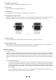
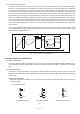
For XLR connector Pin2 (+) Pin2 (+) Pin3 (-) Pin3 (-) (Linked to Pin1 manually, ) Pin1 ( ) Pin1 ( ) XLR Type Unbalanced XLR Type Balanced Pic. 4 b. In Line Connection Please see following drawing for details.
6. TECHNICAL SPECIFICATIONS AUDIO INPUT Type Impedance Active balanced XLR and 1/4"JACK Balanced: 50K Ohm Unbalanced: 25K Ohm Operating Level +4dBu /-10dBv Balanced and Unbalanced: +21 dBu >55dB @1KHz XLR and 1/4" JACK Balanced: 60Ohm Unbalanced: 30Ohm +21 dBu 20Hz to 20KHz at +0,-0.5dB 0.01% typ.1KHz ,@+4dBu 0.04% typ,1KHz ,@+20dBu 0.
7. WARRANTY 1. WARRANTY REGISTRATION CARD To obtain Warranty Service, the buyer should first fill out and return the enclosed Warranty Registration Card within 10 days of the Purchase Date. All the information presented in this Warranty Registration Card gives the manufacturer a better understanding of the sales status, so as to purport a more effective and efficient after-sales warranty service.
SEKAKU ELECTRON IND. CO., LTD NO.1, LANE 17, SEC. 2, HAN SHI WEST ROAD, TAICHUNG, 401 TAIWAN http://www.altoproaudio.com Tel:886-4-22313737 email: alto@altoproaudio.com Fax:886-4-22346757 All rights reserved to ALTO. All features and content might be changed without prior notice. Any photocopy, translation, or reproduction of part of this manual without written permission is forbidden.