Advenger™, Advenger™ AXP BR 600S series Instructions For Use Instrucciones de uso Advance MODELS 56314000(2400D), 56314001(2600D), 56314002(2810D), 56314003(3210D) 56314004(2400C), 56314005(2600C), 56314006(2810C), 56314007(3210C) 56314992(2810D-AXP), 56314993(3210D-AXP), 56314994(2810C-AXP), 56314995(3210C-AXP) Nilfisk MODELS 56314010(600S), 56314011(650S), 56314012(700S), 56314013(800S) 56314014(600SC), 56314015(650SC), 56314016(700SC), 56314017(800SC) 56316517(600S EDS), 56314996(700S EDS), 56314997(800
A-2 / ENGLISH TABLE OF CONTENTS page Introduction ........................................................................................... A-2 Cautions and Warnings ........................................................................ A-3 Consignes de prudence et de sécurité ................................................. A-4 Know Your Machine .............................................................................. A-5 Control Panel .............................................................
ENGLISH / A-3 CAUTIONS AND WARNINGS SYMBOLS Nilfisk-Advance uses the symbols below to signal potentially dangerous conditions. Always read this information carefully and take the necessary steps to protect personnel and property. DANGER! Is used to warn of immediate hazards that will cause severe personal injury or death. WARNING! Is used to call attention to a situation that could cause severe personal injury.
A-4 / ENGLISH CONSIGNES DE PRUDENCE ET DE SÉCURITÉ SYMBOLES Les symboles reproduits ci-dessous sont utilisés pour attirer l’attention de l’opérateur sur des situations dangereuses. Il est donc conseillé de lire attentivement ces indications et de prendre les mesures adéquates en vue de protéger le personnel et le matériel. DANGER! Ce symbole est utilisé pour mettre l’opérateur en garde contre les risques immédiats pouvant provoquer des dommages corporels graves, voire entraîner la mort.
ENGLISH / A-5 KNOW YOUR MACHINE As you read this manual, you will occasionally run across a bold number or letter in parentheses - example: (2). These numbers refer to an item shown on these pages unless otherwise noted. Refer back to these pages whenever necessary to pinpoint the location of an item mentioned in the text. NOTE: Refer to the service manual for detailed explanations of each item illustrated on the next 2 pages.
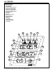
A-6 / ENGLISH CONTROL PANEL A B C D E F G H I J K L M N O P Q R Scrub OFF Indicator Scrub OFF Switch Scrub Pressure Decrease Indicator Scrub Pressure Decrease Switch Scrub Pressure Increase Indicator Scrub Pressure Increase Switch Scrub Pressure / Hourmeter Display Wand Switch Indicator Wand Switch Key Switch Battery Condition Indicator Speed Select Switch Speed Select Indicator Horn Switch Vacuum Switch Vacuum System Indicator Solution System Indicator Solution Switch A B C D E F R Q P G O H N
ENGLISH / A-7 DESCRIPTION OF THE BATTERY CONDITION INDICATORS The battery condition indicator (K) consists of three lights, a green, a yellow, and a red. The voltage indication will change based on the cutoff level (standard or alternate) selected in the control unit. The battery voltage ranges for the various indications are listed below: Standard Alternate Green 34.00+ 34.50+ Green & Yellow 33.00-33.99 34.00-34.49 Yellow 32.00-32.99 33.50-33.99 Yellow & Red 31.50-31.99 33.00-33.49 Red 31.00-31.49 32.
A-8 / ENGLISH INSTALL THE BRUSHES (DISC SYSTEM) CAUTION ! Turn the key switch off (O) and remove the key, before changing the brushes, and before opening any access panels. 1 2 Make sure the Key Switch (J) is off (O). To access the brushes, remove both side skirt assemblies. Note: The skirts are held in place by a two large Knobs, loosen these knobs and slide the skirt assemblies off of the Scrub Deck.
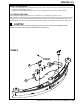
ENGLISH / A-9 INSTALL THE SQUEEGEE 1 2 Make sure the Squeegee (19) is up (O) and the Key Switch (J) is off (O). Hold the squeegee tool so that the curved ends point forward, then slide the squeegee tool onto the Mount (A) (See Figure 2). Hand tighten the Thumb Nuts (B) and then connect the vacuum hose to the Squeegee Tube (C) (vacuum hose should loop to the right).
A-10 / ENGLISH DETERGENT SYSTEM PREPARATION AND USE (AXP/EDS MODELS ONLY) COMMON INSTRUCTIONS: The system should be purged of previous detergent when switching to a different detergent. SERVICE NOTE: Move machine over floor drain before purging because a small amount of detergent will be dispensed in the process. To Purge When Changing Chemicals: 1 Disconnect and remove the detergent cartridge.
ENGLISH / A-11 DETERGENT SYSTEM PREPARATION AND USE (AXP/EDS MODELS ONLY) S T FRONT U AA BB revised 3/06 FORM NO.
A-12 / ENGLISH OPERATING THE MACHINE WARNING ! Be sure you understand the operator controls and their functions. While on ramps or inclines, avoid sudden stops when loaded. Avoid abrupt sharp turns. Use low speed down hills. Clean only while ascending (driving up) the ramp. To Scrub... Follow the instructions in preparing the machine for use section of this manual.
ENGLISH / A-13 AFTER USE 1 2 3 4 5 6 7 When finished scrubbing, press the Scrub Off Switch (B) twice, this will automatically raise, retract and stop all the machine systems (brush, squeegee, vacuum, solution and detergent (AXP/EDS models)). Then drive the machine to a service area for daily maintenance and review of other needed service up keep. To empty the solution tank, remove the Solution Drain Hose (4) from its storage clamp. Direct the hose to a designated “DISPOSAL SITE” and remove the plug.
A-14 / ENGLISH CHARGING THE BATTERIES Charge the batteries each time the machine is used, or whenever the Battery Condition Meter (K) is showing a yellow , red or flashing red indicator light(s). To Charge the Batteries... 1 Depress the Battery Disconnect (13). 2 Open the Battery Compartment Cover (16) to provide proper ventilation. 3 Push the connector from the charger into the Battery Connector (22). 4 Follow the instructions on the battery charger.
ENGLISH / A-15 SQUEEGEE MAINTENANCE If the squeegee leaves narrow streaks or water, the blades may be dirty or damaged. Remove the squeegee, rinse it under warm water and inspect the blades. Reverse or replace the blades if they are cut, torn, wavy or worn. To Reverse or Replace the Rear Squeegee Wiping Blade... 1 See Figure 3. Raise the squeegee tool off the floor, then unsnap the Center Latch (A) on the squeegee tool. 2 Remove the Tension Straps (B). 3 Slip the rear blade off the alignment pins.
A-16 / ENGLISH SIDE SKIRT MAINTENANCE (DISC SYSTEM) The side skirt’s function is to channel the waste water to the squeegee, helping contain the water within the machines cleaning path. During normal use the blades will wear in time. The operator will notice a small amount of water leaking out underneath the side skirts. A height adjustment can easily be made to lower the blades so that all the water can be pick-up by the squeegee. To reverse or replace the scrub system side skirt(s) ... 1 See Figure 4.
ENGLISH / A-17 SIDE SKIRT MAINTENANCE (CYLINDRICAL SYSTEM) The side skirts function is to channel the waste water to the squeegee, helping contain the water within the machines cleaning path. During normal use the blades will wear in time. The operator will notice a small amount of water leaking out underneath the side skirts. Skirt height adjustment is automatic on this system. The skirt assemblies should move up and down freely for proper operation. To replace the scrub system side skirt(s) ...
A-18 / ENGLISH GENERAL MACHINE TROUBLESHOOTING Problem Possible Cause Remedy Poor water pick-up Worn or torn squeegee blades Squeegee out of adjustment Recovery tank full Recovery tank drain hose leak Recovery tank cover gasket leak Debris caught in squeegee Vacuum hose clogged Using too much solution Foam filter cover not seated Reverse or replace Adjust so blades touch floor evenly across entire width Empty recovery tank Secure drain hose cap or replace Replace gasket / Seat cover properly Clean sque
ENGLISH / A-19 TECHNICAL SPECIFICATIONS (as installed and tested on the unit) Model BR 600S BR 650S BR 700S BR 800S dB(A)/20μPa lbs / kg Advenger™ 2400D 56314010 56314000 36V 305 IPX3 65 1,380 / 626 Advenger™ 2600D 56314011 56314001 36V 305 IPX3 65 1,385 / 628 Advenger™ 2810D 56314012 56314002 36V 305 IPX3 65 1,385 / 628 Advenger™ 3210D 56314013 56314003 36V 305 IPX3 65 1,390 / 630 m/s2 1.03m/s2 1.03m/s2 1.03m/s2 1.03m/s2 m/s 0.24m/s 0.24m/s 0.24m/s 2 0.24m/s2 Model No.
B-2 / ESPAÑOL ÍNDICE página Introducción .......................................................................................... B-2 Precauciones y advertencias................................................................ B-3 Conozca su máquina ............................................................................ B-4 Panel de control.................................................................................... B-5 Preparación de la máquina para el uso Instalación de las baterías .........
ESPAÑOL / B-3 PRECAUCIONES Y ADVERTENCIAS SÍMBOLOS Nilfisk-Advance utiliza los símbolos que aparecen a continuación para indicar situaciones potencialmente peligrosas. Lea siempre con atención esta información y tome las medidas necesarias para la protección del personal y los objetos. ¡PELIGRO! Se utiliza para advertir de peligros inmediatos que pueden producir graves daños personales o la muerte.
B-4 / ESPAÑOL CONOZCA SU MÁQUINA A lo largo de este manual encontrará números o letras en negrita entre paréntesis – por ejemplo: (2). Estos números se refieren a un objeto que se muestra en dicha página, a menos que se indique lo contrario. Consulte estas páginas siempre que lo necesite para localizar los elementos citados en el texto. NOTA: Consulte el manual de servicio para obtener explicaciones más detalladas de cada objeto ilustrado en las siguientes 2 páginas.
ESPAÑOL / B-5 PANEL DE CONTROL A B C D E F G H I J K L M N O P Q R Indicador de apagado del fregado Interruptor de apagado del fregado Indicador de disminución de la presión de fregado Interruptor de disminución de la presión de fregado Indicador de aumento de la presión de fregado Interruptor de aumento de la presión de fregado Pantalla de presión de fregado/cronómetro Indicador del interruptor de la vara Interruptor de la vara Conmutador de llave Indicador de situación de las baterías Interruptor de sele
B-6 / ESPAÑOL DESCRIPCIÓN DE LOS INDICADORES DE SITUACIÓN DE LAS BATERÍAS El indicador de situación de las baterías (K) consta de tres luces: una verde, una amarilla y una roja. La indicación de la tensión cambiará en función del nivel máximo (estándar o alternativo) seleccionado en la unidad de control.
ESPAÑOL / B-7 INSTALACIÓN DE LOS CEPILLOS (SISTEMA DE DISCO) ¡PRECAUCIÓN! Apague el interruptor de llave (O) y quite la llave antes de cambiar los cepillos y antes de abrir cualquiera de los paneles de acceso. 1 2 Asegúrese de que está apagado (O) el conmutador de llave (J). Para llegar a los cepillos, retire los conjuntos de faldillas de los dos lados. Nota: Las faldillas está sujetas a cada lado con dos botones grandes, afloje dichos botones y retire los conjuntos de faldillas del portacepillos.
B-8 / ESPAÑOL REPARACIÓN Y USO DEL SISTEMA DE DETERGENTE (AXP/EDS) INSTRUCCIONES COMUNES: Elimine del sistema el detergente anteriormente utilizado antes de cambiar a un detergente diferente. NOTA DE SERVICIO: Desplace la máquina sobre un punto de drenaje en el suelo antes de eliminar el detergente porque saldrá una pequeña cantidad durante el proceso. Purgar al cambiar productos químicos: 1 Desconecte y retire el cartucho de detergente.
ESPAÑOL / B-9 REPARACIÓN Y USO DEL SISTEMA DE DETERGENTE (AXP/EDS) S T FRONT U AA BB revised 3/06 FORM NO.
B-10 / ESPAÑOL MANEJO DE LA MÁQUINA ¡ADVERTENCIA! Asegúrese de que comprende los controles del operador y sus funciones. Si se encuentra sobre una rampa o inclinación, evite las paradas bruscas cuando lleve carga. No tome las curvas bruscamente. Utilice una velocidad lenta si va cuesta abajo. Limpie sólo yendo cuesta arriba. Para fregar... Siga las instrucciones de la sección “Preparación de la máquina para el uso” de este manual.
ESPAÑOL / B-11 DESPUÉS DE LA UTILIZACIÓN 1 2 3 4 5 6 7 Cuando acabe de fregar, pulse el interruptor de apagado del fregado (B) dos veces; esto producirá la elevación, retracción y detención automática de todos los sistemas de la máquina (cepillo, boquilla, aspiración, solución y detergente (modelos AXP/EDS)). A continuación conduzca la máquina a la zona de mantenimiento para el mantenimiento diario y la revisión de otros servicios necesarios.
B-12 / ESPAÑOL RECARGA DE BATERÍAS Recargue las baterías cada vez que se use la máquina o cuando el indicador de la situación de las baterías (K) presente una luz indicadora amarilla, roja o roja intermitente. Para cargar las baterías... 1 Pulse la desconexión de las baterías (13). 2 Abra la cubierta del compartimento de las baterías (16) para que la ventilación sea adecuada. 3 Introduzca el conector del cargador en el Conector de las baterías (22).
ESPAÑOL / B-13 MANTENIMIENTO DE LA BOQUILLA Si la boquilla deja bandas estrechas de agua, puede que las cuchillas estén sucias o dañadas. Retire la boquilla, enjuáguela con agua tibia e inspeccione las cuchillas. Sustituya o invierta las cuchillas si están cortadas, rasgadas, onduladas o gastadas. Para invertir o sustituir la cuchilla secadora de la boquilla trasera... 1 Ver la Figura 3. Levante la boquilla del suelo y, a continuación, desbloquee el pestillo central (A) de la boquilla.
B-14 / ESPAÑOL MANTENIMIENTO DE LA FALDILLA LATERAL (SISTEMA DE DISCOS) La función de las faldillas laterales es canalizar el agua residual hasta la boquilla, lo que ayuda a mantener el agua dentro de la trayectoria de limpieza de la máquina. Es normal que las cuchillas se vayan desgastando con el tiempo. El operador verá que una pequeña cantidad de agua sale por debajo de las faldillas laterales. Puede ajustarse fácilmente la altura para bajar las cuchillas de modo que la boquilla recoja toda el agua.
ESPAÑOL / B-15 MANTENIMIENTO DE LA FALDILLA LATERAL (SISTEMA CILÍNDRICO) La función de las faldillas laterales es canalizar el agua residual hasta la boquilla, lo que ayuda a mantener el agua dentro de la trayectoria de limpieza de la máquina. Es normal que las cuchillas se vayan desgastando con el tiempo. El operador verá que una pequeña cantidad de agua sale por debajo de las faldillas laterales. En este sistema, el ajuste de la altura de las faldillas es automático.
B-16 / ESPAÑOL SOLUCIÓN DE PROBLEMAS GENERALES DE LA MÁQUINA Problema Posible causa Solución Recogida escasa del agua Cuchillas de la boquilla gastadas o Desgarradas Boquilla mal ajustada en toda su anchura Invierta o sustituya las cuchillas Ajuste la boquilla de manera que las cuchillas toquen el suelo de manera uniforme Depósito de recuperación lleno Fuga en la tubería de drenaje del depósito de recuperación Vacíe el depósito de recuperación Sujete la tapa de la tubería de drenaje o sustitúyala Fu
ESPAÑOL / B-17 ESPECIFICACIONES TÉCNICAS (según la instalación y comprobaciones de la unidad) Modelo Nº Modelo Voltaje, baterías Capacidad de baterías Grado de protección Nivel de presión sonora (IEC 60704-1) Peso bruto Vibración en los controles manuales (ISO 5349-1) Vibración en el asiento (EN 1032) Capacidad ascendente Transporte Limpieza V Ah 65 65 65 65 1,385 / 628 1,385 / 628 1,390 / 630 m/s2 1.03m/s2 1.03m/s2 1.03m/s2 1.03m/s2 m/s 0.24m/s 0.24m/s 0.24m/s 2 0.
_____________________________________________________ TYPE: BR600S, BR600SC, BR700S, BR700SC, BR800S, BR800SC BR600S EDS, BR600SC EDS, BR700S EDS, BR700SC EDS, BR800S EDS, BR800SC EDS EU Overensstemmelseserklæring DK Batteridreven gulvaskemaskine Maskinen er fremstillet i overensstemmelse med følgende direktiver: Maskindirektiv: 98/37/EØF EMC-direktiv: 89/336/EØF 92/31/EØF 93/68/EØF 98/13/EOF Lavspændingsdirektiv: 73/23/EØF 93/68/EØF Harmoniserede standarder: EN 60 335-2-72 EU Överensstämmelseförsäkran S, F
ES atbilstības deklarācija LV Grīdas beršanas mašīna ar akumulatoru barošanu Šī mašīna izgatavota atbilstoši šādām direktīvām un standartiem: Mašīnu direktīva: 98/37/EEC Elektromagnētiskās savietojamības (EMC) direktīva: 89/336/EEC 92/31/EEC 93/68/EEC 98/13/EEC Zemsprieguma direktīva: 73/23/EEC 93/68/EEC Saskaņotie standarti: EN 60 335-2-72 Deklaracija EU o skladnosti SL Stroj za čiščenje tal na akumulatorski pogon Ta stroj je izdelan v skladu z naslednjimi smernicami in standardi: Smernica o strojih: 98/37
www.nilfisk-advance.