I N S TA L L AT I O N G U I D E F O R U S E I N M U LT I - C H A N N E L M U S I C O R H O M E T H E A T E R S Y S T E M S HIGH DEFINITION, SIDE/REAR CHANNEL EFFECTS, CEILING MOUNTED LOUDSPEAKER CM6HDFX
NEW CONSTRUCTION CONGRATULATIONS! Thank you for choosing CM6HDfx High-Definition, Side/Rear Channel Effects, Ceiling Mounted Loudspeaker from Niles. With proper installation and operation, you should enjoy years of trouble-free use. Niles manufactures the industry’s most complete line of custom installation components and accessories for audio/video systems. To see the complete Niles product assortment, visit us on the Internet at: www.nilesaudio.
INTRODUCTION Niles CM6HDfx High-Definition, Side/Rear Channel Effects, Ceiling Mounted Loudspeakers are expressly designed for superior sonic quality. They employ advanced technology components that extract the subtle nuances in recorded music or the thunderous action sound in a movie. They are perfect for applications where in-wall or on-wall surround speakers are not practical.
INSTALLER-SELECTABLE ACOUSTIC FINE TUNING Using the baffle-mounted TWEETER LEVEL control, the installer can de-emphasize the treble response by 3 dB after speaker installation to accommodate reflective surfaces and corner loading. MICROPERF™ ALUMINUM GRILLES Niles’ exclusive MicroPerf™ grille construction provides an exceptionally tight hole pattern for acoustic transparency at all audio frequencies and enables the speaker elements to remain invisible.
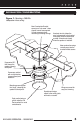
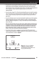
INSTALLATION CONSIDERATIONS Figure 1. Mounting a CM6HDfx loudspeaker into a ceiling. New Construction Bracket serves as a “hole saver” when drywall has not been applied. It is not necessary when retrofitting to existing ceilings. Knockout wire tie allows the wire to be secured to the bracket throughout the new construction process. It knocks out cleanly when the speaker is installed. New construction wings instantly snap into the bracket without screws.
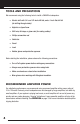
TOOLS AND PRECAUTIONS We recommend using the following tools to install a CM6HDfx loudspeaker: • Electric drill with 1/4- and 1/2-inch drill bits, and a 1-inch flat drill bit (for drilling through studs) • Keyhole or drywall saw • Stiff wire, fish tape, or glow rods (for routing cables) • Phillips screwdriver set • Cable ties • Pencil • Level • Rubber gloves and protective eyewear Before starting the installation, please observe the following precautions: • Turn off all system power before making any connec
LOUDSPEAKER WIRE Use 2-conductor loudspeaker wire when connecting loudspeakers to your receiver or amplifier. For most applications, we recommend using 16- or 18-gauge wire. For wiring runs longer than 80 feet, we recommend 14-gauge wire. The spring-loaded terminals of the CM6HDfx will accommodate up to 12-gauge wire directly. Larger sizes can be accommodated via pin connectors. When running wire inside walls or ceilings, use special jacketed cable (CL-2 or CL-3) to protect the wire and for fire prevention.
PLACEMENT FOR HOME THEATER REAR APPLICATIONS (CONTINUED) soundtrack to create desired effects. However, in a home with a single pair of front speakers, this surround effect will be lost, and jungle sounds may actually sound like they are emanating “from the middle of your head,” just like headphones! A single pair of CM6HDfx Loudspeakers, properly placed, can create a very convincing simulation of an array of surround speakers.
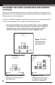
• If you place the surround speakers farther away from the listener, both the reflected and the direct sound will dissipate, requiring even more power from the surroundsound channels. If your sound system uses a small 5- or 10-watt surround amplifier for the rear speakers, be sure to place the speakers within 5 to 8 feet of the listening location.
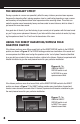
THE BOUNDARY EFFECT Placing a speaker in a corner can powerfully affect the way a listener perceives bass response. Known as the boundary effect, placing speakers close to a wall/ceiling boundary or near a cornerwall boundary will emphasize certain bass frequencies while canceling others. This effect can make the speaker sound excessively boomy and inaccurate to some listeners, while to others it just seems like more bass sound.
DIFFUSE DIRECT USING THE TWEETER LEVEL CONTROL After installation, the installer can de-emphasize the treble response by 3 dB to accommodate reflective surfaces and corner loading by setting the baffle-mounted TWEETER LEVEL control to –3 dB, as shown in Figure 8. -3dB TWEETER LEVEL 0dB Figure 8. The CM6HDfx TWEETER LEVEL control has two response settings.
SCHEDULING AND PREPARATION Plan to schedule the speaker wiring after the electrical wiring is finished. That way you can avoid wire routes, which could potentially induce hum over the speaker wire. The basic wiring rules are: • Never run speaker wire through the same hole as an electrical cable. • Never run speaker wire into the same J-box as electrical cable. • Avoid running the speaker wire beside the electrical cable.
ABOUT DRILLING (CONTINUED) IMPORTANT: DO NOT DRILL THROUGH A GLU-LAM OR LOAD-BEARING BEAM WITHOUT THE DIRECTION OF YOUR CONTRACTOR. • Try to line the holes up perfectly, because it makes pulling the wire much easier. A good technique is to snap a chalk line across the face of the studs or against the bottom of the ceiling joists. Then work backward so that you can always see the holes you have already drilled. Paying careful attention to this will save you time later on.
CONCEALING SPEAKER WIRE (CONTINUED) ABOUT EXTERIOR WALLS Concealing wires in exterior walls is more complex, since the walls are stuffed with insulation to protect the house from the heat and cold outside. Moreover, our national building code requires that a horizontal stud placed between the vertical studs break the hollow wall space in exterior walls. This “fire blocking” makes it very difficult to retrofit long lengths of wire.
Figure 11. An example of unobstructed wall space for speaker wiring. When you don’t have access above or below the wall, try to estimate the existing wire and pipe locations from known positions of electrical outlets and plumbed fixtures on both sides of the wall. Take a look at the outside of your house too – sometimes conduit, vents, or drainpipe will provide useful visible clues. Choose the route with the fewest potential obstacles.
CONCEALING SPEAKER WIRE (CONTINUED) CUTTING HOLES In traditional wood stud/drywall construction, first cut the hole for the speaker. Then, in the opening, use a drill with a long bit to auger a route across the ceiling joists. Sometimes, you will need to use a “notching” technique to reach areas the drill bit won’t reach or to turn corners (e.g. down a wall without an accessible attic). Avoid making an irregular hole in the drywall.
INSTALLING THE BRACKET 1. Attach the QuickSnap™ new-construction wings to the bracket by snapping them into the bracket sides. If the length will interfere with corner or eaves, you can shorten the wings by breaking them along the scored lines. NOTE: THE WINGS AND BRACKETS HAVE CENTERING LINES TO SIMPLIFY PLACEMENT OF THE SPEAKERS. 2. Screw one side of the assembled bracket with wings to the joist, using one of the supplied screws.
EXISTING CONSTRUCTION: INSTALLATION OF BRACKETS, FRAMES, AND GRILLES PLANNING THE INSTALLATION IMPORTANT: BEFORE YOU CUT INTO ANY WALL, REVIEW THE SECTIONS SPEAKER PLACMENT ON PAGE 6 AND RUNNING THE SPEAKER WIRE IN NEW CONSTRUCTION ON PAGE 10. BE SURE NOT TO DRILL OR CUT THROUGH EXISTING WIRES, PIPES, OR STRUCTURE. IF YOU FEEL ANY EXTRA RESISTANCE AS YOU ARE DRILLING OR SAWING, STOP! 1. Locate joists by using a stud sensor or by hand knocking.
7. If you are cutting into a plaster ceiling, use masking tape to outline your penciled circle and use a razor to score the plaster down to the lath beneath. Then use a chisel to remove all of the plaster within the taped outline. To actually cut the lath, consider the following two professional methods: • Use a saber saw with a metal cutting blade for the quickest cut.
INSTALLING THE SPEAKERS (CONTINUED) 6. At each speaker, set the DIFFUSE/DIRECT switch according to the desired application (see page 8 for usage). 7. At each speaker, set the TWEETER LEVEL switch according to the desired application (see page 9 for usage). 8. Install grilles into each speaker – they should fit snugly. If they don’t, try loosening the mounting-dog screws. They may have been tightened too much.
playing together will be lacking in bass and sound “phasey.” If you suspect the sound is not right, and you cannot see any markings on the wire, try this simple test: 1. Stand halfway between the speakers. 2. Play some music with the amplifier or radio set to Mono. 3. Listen to the richness of the bass and the loudness of the sound. 4. Turn off the amplifier and reverse the connections on one amplifier channel only. 5. Repeat the listening test with the same volume control setting.
SPECIFICATIONS (CONTINUED) Hole Cut-Out Dimensions 8" diameter Depth Behind Ceiling 3-3/4" (based on 1/2" drywall) Wiring Requirements We recommend using 16- to 18-gauge speaker wire for runs up to 80 feet and 14-gauge speaker wire for runs up to 200 feet. The connectors will accommodate 12- to 22-gauge wire.
DETACH HERE AND RETURN TO: NILES AUDIO CORPORATION WARRANTY REGISTRATION DEPT. P.O.
BLENDING HIGH FIDELITY AND ARCHITECTURE® Niles Audio Corporation 1 2 3 3 1 S . W. 1 3 0 S t r e e t M i a m i , F l o r i d a 3 3 1 8 6 Designed and Engineered in USA Made in China ©2005 Niles Audio Corporation. All rights reser ved. Niles, the Niles logos an d B l e n d i n g H i g h F i d e l i t y a n d A rchitecture are registered trademarks of Niles Audio Corporation. All other trad e m a r k s a r e t h e p r o p e r ty o f t he i r respective owners. P r i n t e d i n C h i n a .