I N S TA L L AT I O N G U I D E 4 Source, 4 Zone audio multizone receiver kit with am/fm tuner ZR-4 SERIES 2 MultiZone Receiver Kit
CONGRATULATIONS! Thank you for purchasing the Niles ZR-4 MultiZone Receiver Kit. With proper installation and operation, you should enjoy years of trouble-free use. Niles manufactures the industry’s most complete line of custom installation components and accessories for audio video systems. To see the complete Niles product assortment, visit us on the Internet at: www.nilesaudio.com.
Introduction The Niles ZR-4 MultiZone Receiver Kit is a four-source, four-zone distributed audio system. The ZR-4 is packaged as a complete kit and includes a MultiZone Receiver with built-in AM/FM tuner, four weather-resistant keypads, a hand-held learning remote control, rack mount ears, and three infrared MicroFlashers® to control the connected audio sources. The system is easily expandable to eight zones with an additional ZR-4 MultiZone Receiver Kit.
Features and Benefits Four-Source, Four-Zone MultiZone Receiver Any of the ZR-4 MultiZone Receiver’s four audio sources can be routed to any of the four zone outputs to provide high-quality entertainment throughout the house Built-In AM/FM Tuner Provides out-of-the-box radio reception without additional components, connections, or programming Weather-Resistant Keypads The ZR-4 MultiZone Receiver Kit comes with four weather-resistant keypads to accommodate installations in moist areas such as bathrooms, s
CONTENTS After unpacking and before installation, the installer should carefully inspect the contents. If any damage is discovered due to shipping, the installer should contact Niles for assistance (see back cover or Warranty Card for contact information.) Also, keep all packing materials in case the product needs to be returned to the factory.
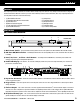
9) G lobal 12V Control Output - A single 3.5mm jack provides a 12V DC trigger signal for use with external components such as an external power amplifier or a Niles AC-3 Voltage-triggered AC Power Strip (sold separately) to automate power turn-on and turn-off of connected components 10) T uner Antenna Inputs - A female coaxial F-connector and two spring-loaded bare-wire jacks provide connection to the included FM and AM antennas 11) RS-232 Connection - One 3.
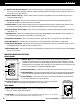
3 Hand-Held Learning Remote Control 1) S ource Select Keys – Pressing one of the keys selects the built-in AM/FM tuner or any of the up to three connected (SRC 2-4) sources for playback and operation. There are also additional Source Select Keys to operate a TV and an auxiliary component such as a DVD player connected to the TV. The LED in the Source Key provides feedback.
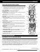
CAT-5 CABLE - T568A Termination The ZR-4 MultiZone Receiver could have as many as five CAT-5 cables connected. Labels are recommended to describe where each cable originates (not to which terminal it connects). The CAT-5 must be terminated with RJ-45 connectors using the T568A wiring convention (Figure 2). 8= BROWN 7= BROWN/WHITE 6= ORANGE 5= BLUE/WHITE 4= BLUE 3= ORANGE/WHITE 2= GREEN 1= GREEN/WHITE Figure 2.
Source Components The ZR-4 MultiZone Receiver has RCA audio inputs for connecting three external source components. In addition to the built-in AM/FM tuner, these three source components can be selected to play in any of the four zones. With this configuration, a user in one zone can listen to a source component while another user in a different zone listens to a different source component (e.g. the CD can be selected in Zone 1 while the AM/FM tuner is selected in Zone 2).
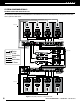
SYSTEM CONFIGURATION 2 Expanding To Eight Zones Using Two ZR-4 Kits This configuration demonstrates the expandability of the ZR-4 MultiZone Receiver Kit. Two complete kits are integrated to create a foursource, eight-zone audio system. CAT-5 Cable Keypad Keypad Keypad Keypad Loudspeakers Loudspeakers Loudspeakers Loudspeakers Speaker Cables ZR-4 Master KEYPADS Expansion MICROFLASHERS® 1 2 3 4 2 AUDIO INPUTS HT Sync 3 L Page AM/FM 4 ZONE 2 ZONE 3 ZONE 4 8 Ω (4 Ω Min.
Expansion Connection This RJ-45 port connects the two ZR-4 MultiZone Receivers with CAT-5 cable using the T568A wiring convention. One ZR-4 MultiZone Receiver will be configured to be the Master, the other to be the Slave. Source Components The audio output of the source components must be routed to both the Master and Slave MultiZone Receivers. This is best accomplished using a Niles AVDA-3 Source Level Stereo Audio/Video Distribution Amplifier (FG00814) for each source.
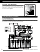
SYSTEM CONFIGURATION 3 ZR-4 Multizone receiver Integrated With A Home Theater System The ZR-4 can share source components with a home theater system. Niles AVDA-3 Distribution Amplifier Cable Box Home Theater Receiver Satellite Receiver CD Player Plugged into Switched AC outlet HT-MSU Niles MF-1 MicroFlashers Audio Cables Flasher Output H.T. Sync Input ZR-4 KEYPADS Expansion 1 MICROFLASHERS® 2 2 AUDIO INPUTS HT Sync 3 3 4 ZONE 1 L Page AM/FM 4 ZONE 2 ZONE 3 8 Ω (4 Ω Min.
SYSTEM CONFIGURATION 4 ZR-4 MultiZone Receiver With External RS-232 Control System The ZR-4 MultiZone Receiver can be monitored and controlled by an external control system that uses RS-232C serial communication. RS-232 Connection A single 3.5mm stereo female-tip positive connector is used for RS-232C serial communication from an external control system. Refer to appendix at www.nilesaudio.com/techsupport for RS-232C integration.
SYSTEM CONFIGURATION 6 ZR-4 multiZone receiver With An External Amplifier In Zone 4 The ZR-4 MultiZone Receiver is designed to accommodate a separate amplifier to drive Zone 4’s loudspeakers. ZR-4 KEYPADS Expansion MICROFLASHERS® 1 2 3 4 2 AUDIO INPUTS HT Sync 3 ZONE 1 L Page AM/FM 4 ZONE 2 ZONE 3 8 Ω (4 Ω Min.) Speaker Outputs 8 Ω (4 Ω Min.) Speaker Outputs 8 Ω (4 Ω Min.) Speaker Outputs 8 Ω (4 Ω Min.
SYSTEM CONFIGURATION 7 ZR-4 MultiZone receiver With System Paging From External Telephone System And/Or DoorBell ZR-4 KEYPADS Expansion 1 MICROFLASHERS® 2 2 AUDIO INPUTS HT Sync 3 Page AM/FM 3 4 ZONE 1 L 4 ZONE 2 12 V Trigger RS 232 IR In Global ZONE 4 8 Ω (4 Ω Min.) Speaker Outputs 8 Ω (4 Ω Min.) Speaker Outputs 8 Ω (4 Ω Min.) Speaker Outputs L+ L+ L+ L- R- R+ R+ L+ L+ L- R- R+ R+ L+ L+ L- R- R+ R+ L- R- R+ R High Output Flasher ZONE 3 8 Ω (4 Ω Min.
SYSTEM INSTALLATION Preparation Before you begin, make sure the audio cables, speaker cables, CAT-5 wiring, MicroFlasher wires and the power supply cable are of sufficient length to reach the ZR-4 MultiZone Receiver. Label each cable describing where each cable originates (rather than to which terminal on the ZR-4 it connects).
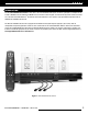
CONNECT THE IR FLASHERS MicroFlasher® to the Flasher Outputs The mini-plug of each included Niles MicroFlasher connects into the Flasher Outputs 2-4. The MicroFlasher portion is placed directly over the IR sensor of the corresponding source component (Source 2 for Flasher 2, Source 3 for Flasher 3, Source 4 for Flasher 4) and adheres with the included adhesive. Remove the protective paper cover to expose the adhesive and attach to the source component.
CONNECT THE GLOBAL 12V OUT The Global 12V Out triggers an external device whenever a Zone is turned on. A common use would be to turn on a 12V trigger-equipped Niles Systems Integration Amplifier connected to the Zone 4 pre-out jacks. The Global 12V out can also be used to trigger a Niles AC-3 Voltage-Triggered AC Power Strip to automate power turn-on and turn-off of connected sources.
KEYPAD INSTALLATION The ZR-4 MultiZone Receiver Kit comes with four weather-resistant, wall-mount Keypads, one for each zone. A zone is an area or room of the house where music is desired, such as a living room, bedroom, kitchen, etc. Each zone is independent and can play any connected music source with its own volume and tone adjustments. Up to two keypads can be installed in each zone (requires ZR-KE Keypad Expander and an additional Solo-4 IR Keypad, both sold separately).
Configuring the MultiZone receiver The Niles ZR-4 MultiZone Receiver Kit is simple to configure. Configuration is accomplished using the front panel buttons and LCD display. No computer is necessary. connected to the Master and not to the Slave. IR from the keypads connected to the Slave chassis will be routed to the Master chassis via the expansion connection port.
to that input until a signal is no longer detected. The paging input will play in all zones at the preset volume. If there are zones that the enduser does not desire to receive a page, follow these steps. While in the configuration mode (see above). Press the Set Key until [ 1234 PAGE MASTER ] shows in the display. A cursor will be blinking under the number “1.” 1234 PPPP PAGE MASTER Press the + key to toggle between the zones to highlight a paging zone.
DEFAULT TURN-ON VOLUME The turn-on volume level for the system is adjustable. Since the turn-on volume level will be the same for all zones, we suggest setting a comfortable listening level in the room that will be used most frequently, or in the smallest room. While in the configuration mode, (see above) press the Set Key until [ DEFAULT TURN ON VOLUME = 60 ] shows in the display. DEFAU LT TURN VOLUME = 60 ON Press the + key to increase the preset volume. Press the – key to decrease the preset volume.
configuring the zone Press the + button to confirm the erase procedure. The display will show [MASTER DEFAULT RESTORED]. MASTER DEFAULT RESTORED Press the – button (at either screen) to exit and move to the next step without erasing any information. To continue to the first configuration step, Master/Slave, press the Set button. To save the settings and exit configuration mode, simultaneously hold down the Band and Set buttons.
Bass Adjustment IR Sensor On/Off A source should be playing through the speakers in the zone. To set the bass adjustment at a zone keypad press and hold the Mute and bottom right Master key simultaneously for three seconds. The bottom right Master key LED will be blinking. By factory default the IR sensor is set to the on position. To turn the keypad’s internal IR sensor on or off, simultaneously press-and-hold the Mute and upper right Master key for three seconds.
Configuring the Hand-Held remote 2. Press a Source key once. To be certain that the remote functions properly, all IR commands for source devices connected to inputs 2, 3, and 4 must be learned from the original device remote. A total of 42 to 75 commands can be stored, depending on the size of the learned commands. Commands for TV and AUX devices are implemented using five-digit codes to identify a complete command set for a device. The codes can be found in the “Manufacturer’s Codes” list provided.
NOTE: If a code digit is 0, the LED does not blink 5. Continue through five digits by pressing 2 for the second digit, 3 for the third, 4 for the fourth and finally 5 for the fifth; counting the TV Source Key LED blinks for each digit. 6. T o check for other device codes, repeat steps 1—5, substituting the source key for the device you would like to check configuring sources 2,3, and 4 These source device commands are learned directly from the original device remotes.
2. Press 9 7 6. The Source Key LED blinks twice 4. Press the key to which you wish to assign a sequence. 3. Press a Source key twice (i.e., TV. VCR/DVD, CBL/ SAT, etc.) to clear all the learned keys for that device. The Source Key LED blinks twice and the R-6L exits from programming mode. 5. Enter the series of commands (Key Presets) you want the sequence to execute (up to 15 commands). Restoring all Key Functions to Factory settings 1.
Operating the ZR-4 MultiZone receiver Play Sources 2-4 1. P ressing any of these source keys will turn on the zone and allow you to listen to the source connected to that input at the preset start volume. Party Mode 2. A dditional control over the source’s functions is available using the R-6L Remote Control. 1. Pressing-and-holding any of the Source Keys on a Keypad for 3 seconds will initiate the Party Mode.
Troubleshooting continued solution: solution: • Call Niles Tech Support • The infrared MicroFlasher® is not connected properly to the back of the receiver • The infrared MicroFlasher® is not affixed properly to the controlled component • The batteries in the hand-held remote control are dead • The IR Sensor is turned off (see page 22) PROBLEM: 6. Poor or no radio reception solution: • Check the receiver’s back panel to see if the FM dipole and AM loop antennas are connected.
Specifications TUNER SECTION CONTROL INTERFACES FM Tuner Keypad Connector Ports Frequency Range: 87.5 – 108 MHz AM Tuner Frequency Range: 530-1710 kHz IF Rejection: >= 40dB Image Rejection: >= 30dB Selectivity: >= 20dB (+/- 20KHz) Usable Sensitivity: <= 63dBu (S/N = 20dB) S/N Ratio: >= 42dB (4) RJ-45 Jacks 12V Control Output 3.5mm female tip-positive IR Control Input 3.5mm female tip-positive Flasher Outputs (2-4) (3) 3.5mm female tip-positive (30mA peak) Flasher Output HP 3.
NOTES NILES AUDIO CORPORATION – 1-800-BUY-HIFI – 305-238-4373 29
Blending High Fidelity And Architecture® Niles Audio Corporation 1 2 3 3 1 S . W. 1 3 0 S t r e e t M i a m i , F l o r i d a 3 3 1 8 6 1-305-238-4373 1 - 8 0 0 - B U Y- H I F I – w w w. n i l e s a u d i o . c o m © 2 0 0 9 N i l e s Au d i o C o r p o r a t i o n . A l l r i g hts r eser v ed .