I N S TA L L AT I O N G U I D E FOR USE IN MULTI-CHANNEL MUSIC OR HOME THEATER SYSTEMS HIGH DEFINITION, LEFT/CENTER/RIGHT CHANNEL, IN-WALL LOUDSPEAKER HDLCR
CONGRATULATIONS! Thank you for choosing the HDLCR High-Definition, Left/Center/Right Channel In-Wall Loudspeaker from Niles. With proper installation and operation, you should enjoy years of trouble-free use. Niles manufactures the industry’s most complete line of custom installation components and accessories for audio/video systems. To see the complete Niles product assortment, visit us on the Internet at: www.nilesaudio.
INTRODUCTION The Niles HDLCR High-Definition, Left/Center/Right Channel, In-Wall Loudspeaker is expressly designed for superior sonic quality in front-, center-, or rear-channel applications. It employs advanced technology components that extract the subtle nuances in recorded music or the thunderous action sound in a movie. The HDLCR is the perfect choice wherever quality of sound is the most important consideration.
INSTALLER-SELECTABLE ACOUSTIC FINE TUNING Using the baffle-mounted TREBLE and BASS CUT controls, the installer can de-emphasize the bass and/ or treble response by 3 dB after installing the HDLCR to precisely tone match the sound in any room. CTR L/R MODE SWITCH The HDLCR includes a baffle-mounted CTR L/R mode switch to optimize performance in applications as either a center channel or left/right loudspeaker for front-channel use.
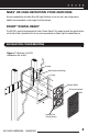
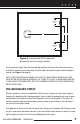
NILES’ HD HIGH-DEFINITION VOICE MATCHING Ensures compatibility with other Niles HD High-Definition in-wall, on-wall, and ceiling-mount models to accommodate a wide range of system designs. DOLBY® DIGITAL READY The HDLCR is specifically designed for Home Theater Sound. This model exceeds the specifications set forth by Dolby Laboratories for the accurate reproduction of Dolby Digital-Encoded Sources. INSTALLATION CONSIDERATIONS Figure 1. Mounting an HDLCR loudspeaker into an wall.
TOOLS AND PRECAUTIONS We recommend using the following tools to install a HDLCR loudspeaker: • Electric drill with 1/4- and 1/2-inch drill bits, and a 1-inch flat drill bit (for drilling through studs) • Keyhole or drywall saw • Stiff wire, fish tape, or glow rods (for routing cables) • Phillips screwdriver set • Cable ties • Pencil • Level • Rubber gloves and protective eyewear Before starting the installation, please observe the following precautions: • Turn off all system power before making any connecti
LOUDSPEAKER WIRE Use 2-conductor loudspeaker wire when connecting loudspeakers to your receiver or amplifier. For most applications, we recommend using 16- or 18-gauge wire. For wiring runs longer than 80 feet, we recommend 14-gauge wire. The spring-loaded terminals of the HDLCR will accommodate up to 12-gauge wire directly. Larger sizes can be accommodated via pin connectors. When running wire inside walls or ceilings, use special jacketed cable (CL-2 or CL-3) to protect the wire and for fire prevention.
INSULATING THE WALL CAVITY For best performance from your speakers, fill the wall cavity behind the speaker with fiberglass insulation (e.g., R-19 un-batted insulation). Try to keep the same amount of insulation for each speaker, particularly in the same room, for consistent bass response. TECH TIP Wire size is expressed by its AWG (American Wire Gauge) number – the lower the number, the larger the wire. For example, 12 AWG is physically larger than 14 AWG.
Speaker Placement Zone 5' 10' 10' Speaker Placement Zone Figure 2. Recommended HDLCR loudspeaker placement for front left and right channels. As for placement height, place front left and right speakers on either side of the picture source so that their tweeters are not more than 24 inches above or below the center-channel speaker’s tweeter (see Figure 3 on page 8). NOTE: DO NOT PLACE AN HDLCR SPEAKER TOO CLOSE TO A DIRECT-VIEW TV MONITOR, AS IT MAY CAUSE PICTURE DISCOLORATION.
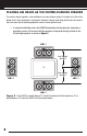
PLACING AN HDLCR AS THE CENTER-CHANNEL SPEAKER The center-channel speaker is the workhorse in a home theater system. It handles all of the critical dialog and is vitally important in creating the illusion of sounds emanating directly from the picture. Here are some tips for obtaining optimum center-channel performance: • In a typical installation, place the HDLCR horizontally, directly above the television or projection screen.
• For installations where a perforated projection screen will be used, place the HDLCR, either horizontally or vertically, behind the screen at ear level, as shown in Figure 4. Perforated Screen HDLCR HDLCR HDLCR Figure 4. Recommended HDLCR center-channel placement behind a perforated projection screen.
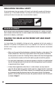
RUNNING THE SPEAKER WIRE IN NEW CONSTRUCTION (CONTINUED) SCHEDULING AND PREPARATION Plan to schedule the speaker wiring after the electrical wiring is finished. That way you can avoid wire routes, which could potentially induce hum over the speaker wire. The basic wiring rules are: • Never run speaker wire through the same hole as an electrical cable. • Never run speaker wire into the same J-box as electrical cable. • Avoid running the speaker wire beside the electrical cable.
• When drilling holes in ceiling joists, drill in the center of the joists and try to locate the hole near the end of the joist. IMPORTANT: DO NOT DRILL THROUGH A GLU-LAM OR LOAD-BEARING BEAM WITHOUT THE DIRECTION OF YOUR CONTRACTOR. • Try to line the holes up perfectly, because it makes pulling the wire much easier. A good technique is to snap a chalk line across the face of the studs or against the bottom of the ceiling joists.
CONCEALING SPEAKER WIRE (CONTINUED) ABOUT EXTERIOR WALLS Concealing wires in exterior walls is more complex, since the walls are stuffed with insulation to protect the house from the heat and cold outside. Moreover, our national building code requires that a horizontal stud placed between the vertical studs break the hollow wall space in exterior walls. This “fire blocking” makes it very difficult to retrofit long lengths of wire.
Figure 7. An example of unobstructed wall space for speaker wiring. When you don’t have access above or below the wall, try to estimate the existing wire and pipe locations from known positions of electrical outlets and plumbed fixtures on both sides of the wall. Take a look at the outside of your house too – sometimes conduit, vents, or drainpipe will provide useful visible clues. Choose the route with the fewest potential obstacles.
CONCEALING SPEAKER WIRE (CONTINUED) CUTTING HOLES In traditional wood stud/drywall construction, first cut the hole for the speaker. Then, in the opening, use a drill with a long bit to auger a wire route up or down the wall. Next, cut a hole in the drywall for stud access, drill holes through the studs, and run your wire, as shown in Figure 9. After the wire has been run, patch the hole with the cut drywall using standard drywall joint tape and joint compound.
4 Wire Ties Figure 10. The hole-saving brackets with QuickSnap new-construction wings can be installed horizontally or vertically. 2. Screw one side of the assembled bracket with wings to the stud or joist, using one of the supplied screws. Level the bracket, and then screw the other side of the bracket/wing assembly to the stud or joist. Two screws on each side make for a very secure installation. 3. Attach the wire to the bracket at the indicated wire tie points, as shown in Figure 10.
EXISTING CONSTRUCTION: INSTALLING A BRACKET IMPORTANT: BEFORE YOU CUT INTO ANY WALL, REVIEW THE SECTIONS ON SPEAKER PLACEMENT ON PAGE 6 AND RUNNING THE SPEAKER WIRE IN NEW CONSTRUCTION ON PAGE 9. BE SURE NOT TO DRILL OR CUT THROUGH EXISTING WIRES, PIPES, OR STRUCTURE. IF YOU FEEL ANY EXTRA RESISTANCE AS YOU ARE DRILLING OR SAWING, STOP! 1. Locate studs or joists by using a stud sensor or by hand knocking.
FINISHING THE INSTALLATION PAINTING THE GRILLE AND FRAME After drywall is up, each HDLCR frame and grille may be painted without the need for primer. For best results, use a spray gun or airless sprayer, thin the paint to prevent clogging of the grille holes, and apply several light coats instead of one heavy one. 1. Paint each grille and let it dry before installation. 2. Paint each frame and let it dry before installation. INSTALLING THE FRAME 1. Fill each wall cavity with insulation.
INSTALLING A NILES MS-100 MICROSENSOR® 1. For each speaker, locate the half-inch round, molded “IR Sensor Knockout” on the baffle. 2. Lay each speaker face down on a clean carpet or rug. Put the tip of a screwdriver into the center of the round “knockout” and sharply tap the screwdriver handle as necessary. NOTE: TO PREVENT DAMAGE TO THE CROSSOVER NETWORK, ALWAYS REMOVE A KNOCKOUT FROM THE REAR OF THE SPEAKER. DO NOT ATTEMPT TO REMOVE A KNOCKOUT WITH THE SPEAKER FACE UP. 3.
CONNECTING AND INSTALLING THE SPEAKER 1. At each speaker, separate the speaker wire so that at least 2 inches of each conductor are free. Strip away 1/4 inch of insulation from each speaker wire. 2. On each set of speaker connectors, press down the spring-loaded lever, insert the appropriate conductor, and then release the lever, as shown in Figure 15. Gently tug on the speaker wire to make sure it is held in place. If not, repeat this procedure until it is.
CONNECTING AND INSTALLING THE SPEAKER (CONTINUED) IMPORTANT: WHEN INSTALLING THE SPEAKERS IN THE CEILING, OR IF THE INSTALLATION IS IN AN EARTHQUAKE ZONE, WE RECOMMEND USING THE ENCLOSED SHEET METAL SCREWS TO SECURE THE BAFFLE TO THE FRAME AS FOLLOWS: a. Locate the dimples on the front baffle. b. Place the self-tapping sheet-metal screw in the dimple and turn it with a screwdriver until it cuts through the baffle and anchors securely in the frame, as shown in Figure 17. Figure 17.
1. Stand halfway between the speakers. 2. Play some music with the amplifier or radio set to Mono. 3. Listen to the richness of the bass and the loudness of the sound. 4. Turn off the amplifier and reverse the connections on one amplifier channel only. 5. Repeat the listening test with the same volume control setting. When the sound has a richer bass and is slightly louder, the speakers are working together or “in-phase.
ADJUSTING THE TWEETER (CONTINUED) 3. Pivot the tweeter on each speaker equally by depressing the housing at the arrows until the desired angle is achieved, as shown in Figure 20. INSTALLING THE GRILLE At each speaker, carefully fit the grille into its recess so that it is barely in place. Starting with one corner, gently press the grille around the speaker, pushing it in a little bit each time. Be gentle – the aluminum grille can be easily bent out of shape.
REMOVING THE SPEAKER 180 ww 1-8 0w.n 00 BU iles -28 Yau 9-4 HI dio 43 FI .co 4 m After removing the grille, use two small screwdrivers (or needle-nose pliers) to release the snaps that hold the speaker (and baffle) to the frame. Insert the screwdrivers into the holes in the snaps and exert force straight down (towards the woofer) until the snaps release, as shown in Figure 21. 1- ww 1- 80 0w. 80 BU nil 0es 28 Yau 9- H dio44 IF 34 I .co m Figure 21. Removing the HDLCR speaker baffle from its frame.
LIMITED WARRANTY NILES AUDIO CORPORATION (“NILES”) WARRANTS ITS LOUDSPEAKER PRODUCTS TO THE ORIGINAL PURCHASER TO BE FREE OF MANUFACTURING DEFECTS IN MATERIAL AND WORKMANSHIP FOR A PERIOD OF FIVE YEARS FROM DATE OF PURCHASE. THIS WARRANTY IS SUBJECT TO THE FOLLOWING ADDITIONAL CONDITIONS AND LIMITATIONS.
DETACH HERE AND RETURN TO: NILES AUDIO CORPORATION WARRANTY REGISTRATION DEPT. P.O.
BLENDING HIGH FIDELITY AND ARCHITECTURE® Niles Audio Corporation 1 2 3 3 1 S . W. 1 3 0 S t r e e t M i a m i , F l o r i d a 3 3 1 8 6 Designed and Engineered in USA Made in China ©2005 Niles Audio Corporation. All rights reser ved. Niles, the Niles logos an d B l e n d i n g H i g h F i d e l i t y a n d A rchitecture are registered trademarks of Niles Audio Corporation. All other trad e m a r k s a r e t h e p r o p e r ty o f t he i r respective owners. P r i n t e d i n C h i n a .