
Reference Manual
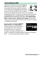
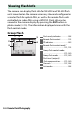
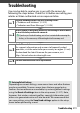

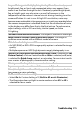
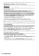
Table Of Contents
- Package Contents
- Table of Contents
- For Your Safety
- Notices
- Getting to Know the Camera
- First Steps
- Basic Photography and Playback
- Basic Settings
- Shooting Controls
- The i Menu
- More About Playback
- Menu Guide
- Defaults
- The Playback Menu: Managing Images
- The Photo Shooting Menu: Shooting Options
- Reset Photo Shooting Menu
- Storage Folder
- File Naming
- Choose Image Area
- Image Quality
- Image Size
- NEF (RAW) Recording
- ISO Sensitivity Settings
- White Balance
- Set Picture Control
- Manage Picture Control
- Color Space
- Active D-Lighting
- Long Exposure NR
- High ISO NR
- Vignette Control
- Diffraction Compensation
- Auto Distortion Control
- Flicker Reduction Shooting
- Metering
- Flash Control
- Flash Mode
- Flash Compensation
- Focus Mode
- AF-Area Mode
- Vibration Reduction
- Auto Bracketing
- Multiple Exposure
- HDR (High Dynamic Range)
- Interval Timer Shooting
- Time-Lapse Movie
- Focus Shift Shooting
- Silent Photography
- The Movie Shooting Menu: Movie Shooting Options
- Reset Movie Shooting Menu
- File Naming
- Choose Image Area
- Frame Size/Frame Rate
- Movie Quality
- Movie File Type
- ISO Sensitivity Settings
- White Balance
- Set Picture Control
- Manage Picture Control
- Active D-Lighting
- High ISO NR
- Vignette Control
- Diffraction Compensation
- Auto Distortion Control
- Flicker Reduction
- Metering
- Focus Mode
- AF-Area Mode
- Vibration Reduction
- Electronic VR
- Microphone Sensitivity
- Attenuator
- Frequency Response
- Wind Noise Reduction
- Headphone Volume
- Timecode
- Custom Settings: Fine-Tuning Camera Settings
- Reset Custom Settings
- a: Autofocus
- a1: AF-C Priority Selection
- a2: AF-S Priority Selection
- a3: Focus Tracking with Lock-On
- a4: Auto-Area AF Face/Eye Detection
- a5: Focus Points Used
- a6: Store Points by Orientation
- a7: AF Activation
- a8: Limit AF-Area Mode Selection
- a9: Focus Point Wrap-Around
- a10: Focus Point Options
- a11: Low-Light AF
- a12: Built-in AF-Assist Illuminator
- a13: Manual Focus Ring in AF Mode
- b: Metering/Exposure
- c: Timers/AE Lock
- d: Shooting/Display
- e: Bracketing/Flash
- f: Controls
- g: Movie
- The Setup Menu: Camera Setup
- Format Memory Card
- Save User Settings
- Reset User Settings
- Language
- Time Zone and Date
- Monitor Brightness
- Monitor Color Balance
- Viewfinder Brightness
- Viewfinder Color Balance
- Control Panel Brightness
- Limit Monitor Mode Selection
- Information Display
- AF Fine-Tune
- Non-CPU Lens Data
- Clean Image Sensor
- Image Dust Off Ref Photo
- Image Comment
- Copyright Information
- Beep Options
- Touch Controls
- HDMI
- Location Data
- Wireless Remote (WR) Options
- Assign Remote (WR) Fn Button
- Airplane Mode
- Connect to Smart Device
- Connect to PC
- Wireless Transmitter (WT-7)
- Conformity Marking
- Battery Info
- Slot Empty Release Lock
- Save/Load Settings
- Reset All Settings
- Firmware Version
- The Retouch Menu: Creating Retouched Copies
- My Menu/Recent Settings
- Connections
- On-Camera Flash Photography
- Remote Flash Photography
- Troubleshooting
- Technical Notes
- The Camera Display and Control Panel
- The Nikon Creative Lighting System
- Other Accessories
- Caring for the Camera
- Caring for the Camera and Battery: Cautions
- Specifications
- NIKKOR Z 24–70mm f/4 S Lens User’s Manual
- FTZ Mount Adapter User’s Manual
- Approved Memory Cards
- Memory Card Capacity
- Battery Endurance
- Index
- Changes Made via Firmware Updates

389Remote Flash Photography
Quick Wireless Control
Remote Repeating
1 Displayed in radio AWL when all flash units are ready.
2 Optical AWL is indicated by Y, radio AWL by Z, joint optical and radio AWL by Y and Z.
Optical AWL channel for joint optical and radio AWL is displayed only when SB-500 is used as
master flash.
3 Icons are displayed for each group when joint optical and radio AWL is used.
4 Displayed only when radio AWL or join optical and radio AWL is used.
7
3
8
21
6
5
4
1 Flash-ready indicator
1
............... 368
2 Remote flash control .................192
FP indicator.................................. 269
3 Remote flash control mode
2
.............................................. 191, 192
4 A : B ratio.............................. 374, 382
5 Flash compensation.......... 374, 382
6
Group C flash control mode
and flash level (output)
...374, 382
7 Channel
2
.............................. 191, 368
8 Link mode
4
................................... 368
7
4
8
6
231
5
1 Flash-ready indicator
1
............... 368
2 Remote flash control .................192
3 Flash level (output) ........... 376, 384
4 Remote flash control mode
2
.............................................. 191, 192
5
Number emitted (times)
...376, 384
Frequency............................ 376, 384
6 Group status
(enabled/disabled) .......... 376, 384
7 Channel
2
.............................. 191, 368
8 Link mode
4
................................... 368