
Installation Instructions
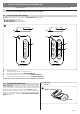
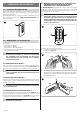
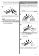
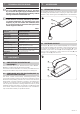

Table Of Contents

ENGLISH – 3
PRODUCT DESCRIPTION AND INTENDED USE
2
2 PRODUCT DESCRIPTION AND INTENDED USE
Transmitters of the series MYGO (MYGO/A) are designed to control automations (gates, garage doors, road barriers and similar).
a
CAUTION! – Any use other than that specied herein or in environmental conditions other than those stated in this
manual is to be considered improper and is strictly forbidden!
2.1 LIST OF CONSTITUENT PARTS
“Figure 1” shows the main parts making up MYGO (MYGO/A) transmitters.
The range consists of two models:
– MYGO4 (MYGO4/A) with four buttons
– MYGO8 (MYGO8/A) with eight buttons.
MYGO4 - MYGO4/A
C
A
B
A
5
1
2
3
4
6
7
8
MYGO8 - MYGO8/A
E
D
A
B
A
1
A Red signalling LED
B Hole for unlocking and removing the rear shell
C Control buttons area for models MYGO4 (MYGO4/A)
D Control buttons area rst sector (*) for models MYGO8 (MYGO8/A)
E Control buttons area second sector (*) for models MYGO8 (MYGO8/A)
(*) Each sector can be regarded as if it were an independent transmitter.
2.2 TRANSMITTER FUNCTIONS
MYGO (MYGO/A) Transmitters are factory-programmed for being
used with receivers that adopt the “O-Code” one-way radio encoding
system (“O-Code/A”). This encoding system allows for exploiting all
the advanced and exclusive functions of the “NiceOpera” system.
Moreover, for the markets that require them and prior suitable pro
-
gramming, the ET Blue, Peccinin, Linear encoding systems can be
supported (refer to the paragraph “ENCODING SWITCH PROCE
-
DURE” on page 5).
MYGO (MYGO/A) transmitters can be programmed with the ProView
device (Figure 2).
ProView
MYGO - MYGO/A
2