
Installation Guide
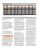

120 psi) are shown in Table 3. These
pressure ratings should be used only
when the correct capillary space has
been maintained.
FLUXES
The fluxes used for brazing copper
joints are different in composition from
soldering fluxes. The two types cannot
be used interchangeably.
Brazing fluxes are water based;
whereas, most soldering fluxes are
petroleum based. Similar to soldering
fluxes, brazing fluxes dissolve and
remove residual oxides from the metal
surface, protect the metal from
reoxidation during heating and promote
wetting of the surfaces to be joined by
the brazing filler metal.
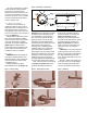
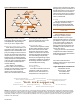
Brazing fluxes also provide the
craftsman with an indication of tem-
perature (Figure 13b). If the outside of
the fitting and the heat-affected area of
the tube are covered with flux (in
addition to the end of the tube and the
fitting cup), oxidation will be minimized
and the appearance of the joint will be
greatly improved.
The fluxes best suited for brazing
copper and copper alloy tube should
meet the requirements of AWS Stan-
dard A5.31, Type FB3-A or FB3-C.
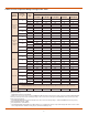
Figure 14 illustrates the need for
brazing flux with different types of
copper and copper-alloy tube, fittings
and filler metals when brazing.
Assembly
Assemble the joint by inserting the
tube into the socket against the stop
and turn if possible. The assembly
should be firmly supported so that it
will remain in alignment during the
brazing operation.
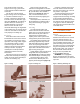
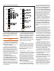
Applying Heat and Brazing
Apply heat to the parts to be joined,
preferably with an oxy-fuel torch with a
neutral flame. Air-fuel is sometimes
used on smaller sizes. Heat the tube
first, beginning about one inch from
the edge of the fitting, sweeping the
flame around the tube in short strokes
at right angles to the axis of the tube
(Figure 12, position 1).
It is very important that the flame
be kept in motion and not remain on
any one point long enough to damage
the tube. The flux may be used as a
guide as to how long to heat the tube.
The behavior of flux during the brazing
cycle is described in Figure 13b.
Switch the flame to the fitting at the
base of the cup (Figure 12, position
2). Heat uniformly, sweeping the flame
alternately from the fitting to the tube
until the flux becomes quiet. Avoid
excessive heating of cast fittings, due
to the possibility of cracking.
When the flux appears liquid and
transparent, start sweeping the flame
back and forth along the axis of the
joint to maintain heat on the parts to
be joined, especially toward the base
of the cup of the fitting (Figure 12,
position 3). The flame must be kept
moving to avoid melting the tube or
fitting.
For 1-inch tube and larger, it may
be difficult to bring the whole joint up
to temperature at one time. It fre-
quently will be found desirable to use
an oxy-fuel, multiple-orifice heating tip
to maintain a more uniform tempera-
ture over large areas. A mild preheating
of the entire fitting is recommended for
larger sizes, and the use of a second
torch to retain a uniform preheating of
the entire fitting assembly may be
necessary in larger diameters. Heating
can then proceed as outlined in the
steps above.
Apply the brazing filler metal at a
point where the tube enters the socket
of the fitting. When the proper tem-
perature is reached, the filler metal will
flow readily into the space between the
tube and fitting socket, drawn in by the
natural force of capillary action.
Keep the flame away from the filler
metal itself as it is fed into the joint.
The temperature of the tube and fitting
at the joint should be high enough to
melt the filler metal.
Keep both the fitting and tube
heated by moving the flame back and
forth from one to the other as the filler
metal is drawn into the joint.
When the joint is properly made,
filler metal will be drawn into the fitting
socket by capillary action, and a
continuous fillet of filler metal will be
visible completely around the joint. To
aid in the development of this fillet
6
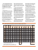
Figure 13. Melting Temperature Ranges
(a) Melting and Brazing Ranges (b) Behavior of Flux during Brazing Cycle