
Installation Guide
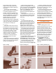
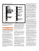

Heat is generally applied using an
air-fuel torch (Figure 9). Such torches
use acetylene or an LP gas. Electric
resistance soldering tools can also be
used (Figure 10). They employ
heating electrodes and should be
considered when an open flame is a
concern.
Applying Solder
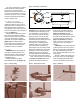
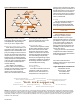
For joints in the horizontal position,
start applying the solder metal slightly
off-center at the bottom of the joint
(Figure 12, position a, and Figure
9). When the solder begins to melt
from the heat of the tube and fitting,
push the solder straight into the joint
while keeping the torch at the base of
the fitting and slightly ahead of the
point of application of the solder.
Continue this technique across the
bottom of the fitting and up one side to
the top of the fitting (Figure 12,
position b).
The now-solidified solder at the
bottom of the joint has created an
effective dam that will prevent the
solder from running out of the joint as
the sides and top of the joint are being
filled.
Return to the point of beginning,
overlapping slightly (Figure 12,
position c), and proceed up the
uncompleted side to the top, again,
overlapping slightly, (Figure 12,
position d). While soldering, small
drops may appear behind the point of
solder application, indicating the joint
is full to that point and will take no
more solder. Throughout this process
you are using all three physical states
of the solder: solid, pasty and liquid.
For joints in the vertical position,
make a similar sequence of overlap-
ping passes starting wherever is
convenient.
Solder joints depend on capillary
action drawing free-flowing molten
solder into the narrow clearance
between the fitting and the tube.
Molten solder metal is drawn into the
joint by capillary action regardless of
whether the solder flow is upward,
downward or horizontal.
Capillary action is most effective
when the space between the surfaces
to be joined is between 0.002 inch
and 0.005 inch. A certain amount of
looseness of fit can be tolerated, but
too loose a fit can cause difficulties
with larger size fittings.
For joining copper tube to solder-
cup valves, follow the manufacturer’s
instructions. The valve should be in the
open position before applying heat,
and the heat should be applied
primarily to the tube. Commercially
available heat-sink materials can also
be used for protection of temperature-
sensitive components during the
joining operation.
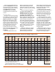
The amount of solder consumed
when adequately filling the capillary
space between the tube and either
wrought or cast fittings may be
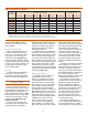
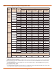
Table 1: Solder Requirements for Solder Joint Pressure Fittings, length in inches
(1)
4
1.
Using
1
/
8
-inch diameter (No. 9) Wire Solder
(1 inch length = .01227 cubic inches).
2.
Actual consumption depends on workmanship.
3.
Includes an allowance of 100% to cover wastage and loss.
NOTE: Flux requirements are usually 2 oz per lb of solder.
Nominal Wt. in lbs
or O.D. Cup at .010
Standard of Depth clearance
Size, Tube, of Fitting, per 100
inches inches inches
0.001 0.002 0.003 0.004 0.005 0.006 0.007 0.008 0.009 0.010
joints
Joint Clearance, inches
1
/
4
.375 .310 .030 .060 .089 .119 .149 .179 .208 .238 .268 .298 .097
3
/
8
.500 .380 .049 .097 .146 .195 .243 .292 .341 .389 .438 .486 .159
1
/
2
.625 .500 .080 .160 .240 .320 .400 .480 .560 .640 .720 .800 .261
5
/
8
.750 .620 .119 .238 .357 .476 .595 .714 .833 .952 1.072 1.191 .389
3
/
4
.875 .750 .168 .336 .504 .672 .840 1.008 1.176 1.344 1.512 1.680 .548
1 1.125 .910 .262 .524 .786 1.048 1.311 1.573 1.835 2.097 2.359 2.621 .856
1
1
/
4
1.375 .970 .341 .683 1.024 1.366 1.707 2.049 2.390 2.732 3.073 3.415 1.115
1
1
/
2
1.625 1.090 .454 .907 1.361 1.814 2.268 2.721 3.175 3.628 4.082 4.535 1.480
2 2.125 1.340 .729 1.458 2.187 2.916 3.645 4.374 5.103 5.833 6.562 7.291 2.380
2
1
/
2
2.625 1.470 .988 1.976 2.964 3.952 4.940 5.928 6.916 7.904 8.892 9.880 3.225
3 3.125 1.660 1.328 2.656 3.985 5.313 6.641 7.969 9.297 10.626 11.954 13.282 4.335
3
1
/
2
3.625 1.910 1.773 3.546 5.318 7.091 8.864 10.637 12.409 14.182 15.955 17.728 5.786
4 4.125 2.160 2.281 4.563 6.844 9.125 11.407 13.688 15.969 18.250 20.532 22.813 7.446
5 5.125 2.660 3.490 6.981 10.471 13.962 17.452 20.943 24.433 27.924 31.414 34.905 11.392
6 6.125 3.090 4.846 9.692 14.538 19.383 24.229 29.075 33.921 38.767 43.613 48.459 15.815
8 8.125 3.970 8.259 16.518 24.777 33.035 41.294 49.553 57.812 66.071 74.330 82.589 26.955
10 10.125 4.000 10.370 20.739 31.109 41.478 51.848 62.218 72.587 82.957 93.326 103.696 33.845
12 12.125 4.500 13.970 27.940 41.910 55.881 69.851 83.821 97.791 111.761 125.731 139.701 45.596
Average
Actual
Consump-
tion
2
For
Estimating
Purposes
3