
Installation Guide
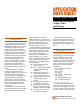
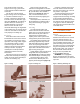
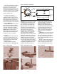
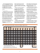
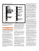
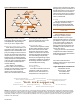

Figure 8. Removing Excess FluxFigure 7. Fluxing: Fitting
Figure 12. Schematic of Solder Joint
Figure 9. Soldering
Figure 11. CleaningFigure 10. Electric Resistance Soldering Tool
3
Use care in applying flux. Careless
workmanship can cause problems
long after the system has been
installed. If excessive amounts of flux
are used, the flux residue can cause
corrosion. In extreme cases, such flux
corrosion could perforate the wall of
the tube, fitting or both.
Assembly and Support
Insert tube end into fitting cup,
making sure that the tube is seated
against the base of the fitting cup . A
slight twisting motion ensures even
coverage by the flux. Remove excess
flux from the exterior of the joint with a
cotton rag (Figure 8).
Support the tube and fitting assem-
bly to ensure an adequate capillary
space around the entire circumference
of the joint. Uniformity of capillary
space will ensure good capillary flow
(Figure 12) of the molten solder
metal. Excessive joint clearance can
lead to solder metal cracking under
conditions of stress or vibration.
Heating
WARNING: When dealing with an
open flame, high temperatures and
flammable gases, safety precautions
must be observed as described in
ANSI/AWS Z49.1.
Begin heating with the flame
perpendicular to the tube (Figure 12,
position 1). The copper tube conducts
the initial heat into the fitting cup for
even distribution of heat in the joint
area. The extent of this preheating
depends upon the size of the joint.
Preheating of the assembly should
include the entire circumference of the
tube in order to bring the entire
assembly up to a suitable preheat
condition. However, for joints in the
horizontal position, avoid directly
preheating the top of the joint to avoid
burning the soldering flux. The natural
tendency for heat to rise will ensure
adequate preheat of the top of the
assembly. Experience will indicate the
amount of heat and the time needed.
Next, move the flame onto the fitting
cup (Figure 12, position 2). Sweep
the flame alternately between the
fitting cup and the tube a distance
equal to the depth of the fitting cup
(Figure 12, position 3). Again,
preheating the circumference of the
assembly as described above, with the
torch at the base of the fitting cup
(Figure 12, position 4), touch the
solder to the joint. If the solder does
not melt, remove it and continue
heating.
CAUTION: Do not overheat the joint
or direct the flame into the face of the
fitting cup. Overheating could burn the
flux, which will destroy its effective-
ness, and the solder will not enter the
joint properly.
When the solder melts, apply heat
to the base of the cup to aid capillary
action in drawing the molten solder
into the cup toward the heat source.