
Manual

NIBCO Technical Services • Phone: 1.888.446.4224 • Fax: 1.888.336.4224
6
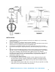
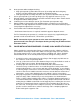
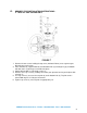
5. Pressurize piping to valve and inspect for leakage. If leakage is observed, tighten
bolts using cross-over pattern, increasing torque until leak stops.
DO NOT EXCEED MAXIMUM TORQUES LISTED IN TABLE 3 BELOW.
6. Recommended torques are made without warranty. Installer must verify proper
strength bolts for application. Bolts shall be cleaned and un-lubricated.
CAUTION:
1. Class 250 cast iron and Class 300 steel flanges cannot be used on these valves.
2. Rubber faced or mechanical flanges are not recommended.
3. This valve is not recommended for steam service.
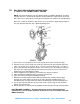
4. Valves should not be assembled to the flanges and then welded into the piping system.
5. Lever-lock handles are not recommended for use on 8” and larger valves.
6. Do not install valves with EPDM liner in compressed air lines.
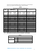
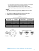
TABLE 3
Recommended Bolt Tightening Torques
Flange Size Bolt Size
Minimum Bolt
Torque (ft./lbs.)
Maximum Bolt
Torque (ft./lbs.)
2” – 4” 5/8” 20 70
5” – 8” 3/4” 30 120
10” and 12” 7/8” 50 200
14” and 16” 1” 70 240
18” and 20” 1-1/8” 100 380
24” – 30” 1-1/4” 140 520
32” – 48” 1-1/2” 200 800
54” – 60” 1-3/4” 350 1800