
Manual

NIBCO Technical Services • Phone: 1.888.446.4224 • Fax: 1.888.336.4224
3
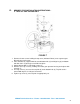
relation to the valve body and piping system. Pre-planning may save from having to
remove a “just installed” valve and reinstalling in another orientation.
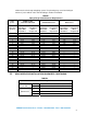
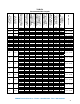
TABLE 1
Piping/Flange Inside Diameter Requirements
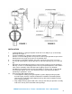
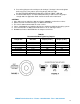
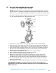
III. GEAR OPERATOR INSTALLATION HANDWHEEL POSITIONING
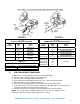
TABLE 2
Tools Required
Fire Protection
(UL/FM)
2” – 8” 9/16” hex wrench and 1/8” hex Allen wrench
10” – 12” 3/4” hex wrench and 1/8” hex Allen wrench
Commercial
2” – 8” 9/16” hex wrench
10” – 14” 3/4” hex wrench
16” – 18” 1-1/8” hex wrench
Valve
Series
LD/WD/LC/WC
1000/2000/3000/5000
LD7000/8000 Series N200 Series
Valve Size
(Inches)
Minimum
Pipe/Flange
ID for Disc
Clearance
Maximum
Pipe/Flange
ID for
Proper Seal
Minimum
Pipe/Flange
ID for Disc
Clearance
Maximum
Pipe/Flange
ID for
Proper Seal
Minimum
Pipe/Flange
ID for Disc
Clearance
Maximum
Pipe/Flange
ID for
Proper Seal
2 2.00 2.49 1.31 2.43 1.38 2.24
2-1/2 2.37 2.86 1.89 3.06 1.95 2.74
3 2.67 3.43 2.64 3.65 2.66 3.33
4 3.69 4.55 3.67 4.75 3.67 4.55
5 4.76 5.62 4.44 5.54 4.48 5.50
6 5.96 6.62 5.96 6.84 5.96 6.66
8 8.01 8.62 7.85 8.89 7.85 8.61
10 10.00 10.80 9.73 10.70 9.76 10.75
12 11.99 13.12 11.71 12.74 11.72 12.79
14 13.16 13.77 13.02 15.50 — —
16 15.34 16.30 15.20 17.90 — —
18 17.23 18.31 17.16 19.67 — —
20 19.04 20.08 19.10 21.05 — —
24 23.05 24.71 23.04 25.57 — —
28 — — 27.10 29.31 — —
30 29.06 30.29 29.08 31.28 — —
32 — — 30.91 33.93 — —
36 33.59 35.78 33.60 36.77 — —
42 39.83 42.77 39.87 44.96 — —
48 44.85 48.27 44.86 51.57 — —
54 — — 50.67 54.25 — —
60 — — 54.93 60.25 — —