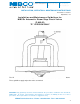
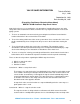
NIBCO INC. 1 5 1 6 M I D D L E B U R Y S T. PHONE: WORLD HEADQUARTERS E L K H A R T, I N 4 6 5 1 6 - 4 7 4 0 FA X : USA WEB: 574.295.3000 574.295.3307 w w w. n i b c o . c o m INSTALLATION, OPERATION & MAINTENANCE INSTRUCTIONS Review Date: 01/18/2012 Original Date: NA Installation and Maintenance Guidelines for NIBCO ® Automatic Steam Stop Check Valves (F-869-B) “D” VERSION ONLY The “D” series valves are identified by the raised letter “D” cast into the bonnet as shown above.
NIBCO Technical Services • Phone: 1.888.446.4224 • Fax: 1.888.336.
NIBCO Technical Services • Phone: 1.888.446.4224 • Fax: 1.888.336.
Guidelines for Disassembly and Cleaning NIBCO® F-869-B Automatic Steam Stop Check Valves The NIBCO F-869-B automatic steam stop check valve is the preferred type of valve used on discharge nozzles of steam boilers in multiple boiler installations. The ANSI/ASME Power Piping Code B31.1 makes reference to this in Section 122.1.7A. Periodically it may become necessary to perform maintenance on these valves to keep them performing at their best.
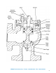
The full operation of this adjustment is only of a turn, 90°, from full open to full close. 5. Remove and discard the gasket between the bonnet and the top lid of the dashpot cylinder. It is not worth the gamble to use an old gasket over again when you consider the valve my leak at the joint afterwards. 6. Mark the dashpot cylinder and body with an ink marker or chalk for alignment when reassembling. The dashpot cylinder may be stuck to the body. Carefully pry the lip of the dashpot cylinder to loosen.
14. Before reassembly make sure all the components are thoroughly clean, particularly gasket surfaces. Check carefully inside the valve body (still mounted on the boiler). It is very important that all foreign particles and residue be removed from the valve. A light lubricant such as kerosene or fuel oil may be used very sparingly for parts difficult to reassemble. A drop or two is plenty. 15. Two new identical gaskets are required – one on top of and one under the lip of the dashpot.
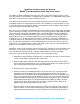
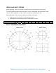
APPENDIX I Body to Bonnet Bolt Installation Procedure for NIBCO® Cast Iron, Alloy Iron and Ductile Iron Valves The following procedure outlines the methods to be used in the assembly of and field installation of the body to bonnet bolts and nuts in order to assure the proper clamping stresses. The correct sequence and torque for tightening the body to bonnet bolts and nuts is also identified.
IRON VALVE BOLT TORQUE Before tightening, make sure all surfaces that the fastener will contact are clean and dry. The torque tightening table listed below applies to clean, undamaged, well lubricated threaded fasteners. When tightening, use the sequence chart below. Tighten in two steps. When tightening, use the sequence chart below. Tighten in two steps. 1. Tighten fastener using about 1/2 the final torque figure. 2. Final tighten using the full torque figure. ASTM A307 steel only.
VALVE SALES INFORMATION Technical Bulletin July 1, 1980 September 26, 1969 Reissued May 20, 1985 (Everything You Always Wanted to Know About) NIBCO F-869-B Automatic Stop-Check Valves Stop-check valves are as essential to the safe operation of a multi-boiler plant as any other safety device that is attached to a boiler, and have four very important functions in the steam piping systems. 1.
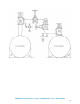
Generally, there are two valves between the boiler and the header. One valve is a stopcheck valve and the other valve is a stop valve, either gate, angle or globe type. The two valves are used to make maintenance more convenient and in most cases, are required by code for the inspectors safety while inspecting the boiler (See sketch).
Finally, we come to the questions – How is this done? How does the dashpot work? How is the adjustment made? The dashpot is the same in principle as a shock absorber on an automobile. It does not prevent, but rather controls the rate of movement. The dashpot must have fluid to displace. In the case of the stop-check, this fluid is the fluid within the piping system, namely steam. All dashpots are very similar to an air cylinder.
dashpot arrangement. It should be pointed out that the stop-check valve must always be in an upright position with the handwheel on top of the valve. If this is not done there is no way that the valve will work in its proper capacity.
Sizing the NIBCO F-869-B Automatic Stop-Check Valve It has been said that the automatic stop-check valve is the most sophisticated valve in the NIBCO line. One reason for this statement is the procedure required to select the proper size stop-check valve for a given installation. The obvious way to determine valve size is to match the pipe diameter. For the stop-check valve this is not correct. In many boiler installations a valve smaller than pipe size could and should be selected.
Theoretical Stop and Check Angle Valve Saturated Stem Flow Rates (Figure Number F-869-B) VALVE SIZE PRESSURE DROP PSI SATURATED STEAM PRESSURE GAGE STEAM VOLUME FLOW POUNDS PER HOUR 2-1/2” 2-1/2” 2-1/2” 2-1/2” 3” 3” 3” 4” 4” 4” 4” 6” 6” 6” 6” 8” 8” 8” 8” 10” 10” 10” 10” 4” 4” 4” 4” 6” 6” 6” 6” 8” 8” 8” 8” 10” 10” 10” 10” 2 2 2 2 2 2 2 2 2 2 2 2 2 2 2 2 2 2 2 2 2 2 2 5 5 5 5 5 5 5 5 5 5 5 5 5 5 5 5 10 50 120 250 10 50 120 10 50 120 250 10 50 120 250 10 50 120 250 10 50 120 250 10 50 120 250 10 50 120 2