
Manual

www.nexusrobot.com Robot Kits manual
3
¾ Memory function
The ATmega328 has 32 KB (with 0.5 KB used for the bootloader). It also has 2 KB of SRAM and 1 KB of
EEPROM (which can be read and written with the EEPROM library).
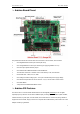
¾ Input and Output PinMode
Each of the 14 digital pins on the Duemilanove can be used as an input or output, using pinMode(),
digitalWrite(), and digitalRead() functions. They operate at 5 volts. Each pin can provide or receive a
maximum of 40 mA and has an internal pull-up resistor (disconnected by default) of 20-50 kOhms. In
addition, some pins have specialized functions:
Serial: 0 (RX) and 1 (TX). Used to receive (RX) and transmit (TX) TTL serial data. These pins are
connected to the corresponding pins of the FTDI USB-to-TTL Serial chip.
External Interrupts: 2 and 3. These pins can be configured to trigger an interrupt on a low value, a rising
or falling edge, or a change in value. See the attachInterrupt()
function for details.
PWM: 3, 5, 6, 9, 10, and 11. Provide 8-bit PWM output with the analogWrite()
function.
SPI: 10 (SS), 11 (MOSI), 12 (MISO), 13 (SCK). These pins support SPI communication using the SPI
library.
LED: 13. There is a built-in LED connected to digital pin 13. When the pin is HIGH value, the LED is on,
when the pin is LOW, it's off.
¾ Communication
The Arduino Uno has a number of facilities for communicating with a computer, another Arduino, or other
microcontrollers. The ATmega328 provides UART TTL (5V) serial communication, which is available on
digital pins 0 (RX) and 1 (TX). An ATmega8U2 on the board channels this serial communication over
USB and appears as a virtual com port to software on the computer. The '8U2 firmware uses the
standard USB COM drivers, and no external driver is needed. However, on Windows, a .inf file is
required. The Arduino software includes a serial monitor which allows simple textual data to be sent to
and from the Arduino board. The RX and TX LEDs on the board will flash when data is being transmitted
via the USB-to-serial chip and USB connection to the computer (but not for serial communication on pins
0 and 1).
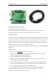
¾ Configuration
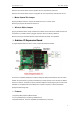
¾ Servo Power Select Jumper
As most servo draw more current than the USB power source can supply. A separate servo power
terminal is provided to power the servo individually which can be Enable/Disable by the Servo Power
Select Jumper.