
Manual
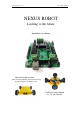

www.nexusrobot.com Robot Kits manual
2
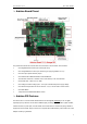
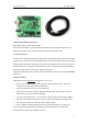
¾ Arduino Board Pinout
The picture above shows all of the I/O lines and Connectors on the controller, which includes:
One Regulated Motor Power Input Terminal (6v to12v)
One Unregulated Servo Power Input Terminal (you supply regulated 4v to 7.2v)
One Servo input power selection jumper
One Serial Interface Module Header for APC220 Module
Two DC Motor Terminals – Handles motor current draw up to 2A, each terminal
One IIC/TWI Port – SDA, SCL, 5V, GND
One Analog Port with 8 analog inputs – one input is tied internally to the supply voltage
One General Purpose I/O Port with 13 I/O lines – 4,5,6,7 can be used to control motors
One Reset Button
Jumper bank to Enable/Disable Motor Control
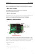
¾ Arduino 328 Features
The Arduino Uno is a microcontroller board based on the ATmega328 (datasheet). It has 14 digital
input/output pins (of which 6 can be used as PWM outputs), 6 analog inputs, a 16 MHz crystal oscillator,
a USB connection, a power jack, an ICSP header, and a reset button. It contains everything needed to
support the microcontroller; simply connect it to a computer with a USB cable or power it with a AC-to-DC
adapter or battery to get started.