
Manual

www.nexusrobot.com Robot Kits manual
35
¾ The PWM signal
In a nutshell, PWM is a way of digitally encoding analog signal levels. Through the use of high-resolution
counters, the duty cycle of a square wave is modulated to encode a specific analog signal level. The
PWM signal is still digital because, at any given instant of time, the full DC supply is either fully on or fully
off. The voltage or current source is supplied to the analog load by means of a repeating series of on and
off pulses. The on-time is the time during which the DC supply is applied to the load, and the off-time is
the period during which that supply is switched off. Given a sufficient bandwidth, any analog value can be
encoded with PWM.
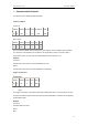
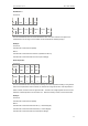
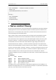
Figure 2 shows three different PWM signals. Figure 1a shows a PWM output at a 10% duty cycle. That is,
the signal is on for 10% of the period and off the other 90%. Figures 1b and 1c show PWM outputs at
50% and 90% duty cycles, respectively. These three PWM outputs encode three different analog signal
values, at 10%, 50%, and 90% of the full strength. If, for example, the supply is 9V and the duty cycle is
10%, a 0.9V analog signal results.
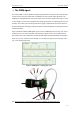
Figure 2. PWM signals of varying duty cycles
motor’s encoder wires
See: http://www.netrino.com/Embedded-Systems/How-To/PWM-Pulse-Width-Modulation