
Manual

www.nexusrobot.com Robot Kits manual
34
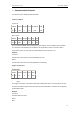
Input = analogRead(0); //initialize the variables we're linked to
Setpoint = 100;
myPID.SetMode(AUTOMATIC); //turn the PID on
}
void loop() {
Input = analogRead(0);
myPID.Compute();
analogWrite(3,Output);
}
See: http://www.arduino.cc/playground/Code/PIDLibrary
¾ Servo control Theory
RC servos are comprised of a DC motor mechanically linked to a potentiometer. Pulse-width modulation
(PWM) signals sent to the servo are translated into position commands by electronics inside the servo.
When the servo is commanded to rotate, the DC motor is powered until the potentiometer reaches the
value corresponding to the commanded position.
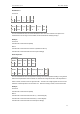
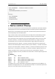
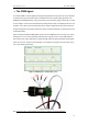
Figure 1 shows The servo motor’s signal wires, there are two bigs and four smalls.following ,we will to
understand how the motor works. we can use these wires to control the motor make servo control.
How to link the Servo motor’s signal wires: The two wires Sticked together used for drive motor: power:
the red one, marked by “+” should be connected to the positive wire from your supply to the screw
terminal labeled “VIN" on the Arduino board. NOTE: Maximum supply voltage cannot exceed 14V
DC.Ground:The black one. marked by “-” should be connected to a ground pin on the Arduino board.
Aother four wires Sticked together is used for encoder: the power: marked by “+” should be connected to
the 5V pin on the Arduino board . the Ground : marked by ”-” should be connected to a ground pin on the
Arduino board. The signal pins: Pin A marked “A”, should be connected to a digital pin which one you
defined on the Arduino board . It used for input command to motor. Pin B:marked “B”. should be
connected to a digital pin which one you defined on the Arduino board . It used for output the signal of the
motor runs.
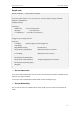
Pin PWM Mode
Pin name Function
Digital 4 M1 Motor 1 Direction control
Digital 5 E1 Motor 1 PWM control (speed control)
Digital 6 M2 Motor 2 PWM control (speed control)
Digital 7 E2 Motor 2 Direction control
The PWM DC motor control is implemented by manipulating two digital IO pins and two PWM pins. As
illustrated in the diagram above, Pin 4,7 are motor direction control pins, Pin 5,6 are motor speed control
pins.Then you can used it to set the motor works as you want.