
Manual


www.nexusrobot.com Robot Kits manual
21
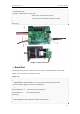
¾ Motor Control
Hardware Setting
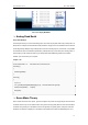
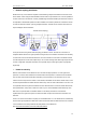
Connect four motor wires to Motor Terminal. And apply power through motor power terminal.
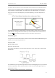
The PWM DC motor control is implemented by manipulating two digital IO pins and two PWM pins. As
illustrated in the diagram above, Pin 4,7 are motor direction control pins, Pin 5,6 are motor speed control
pins.
Pin Allocation
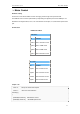
PWM Control Mode
"PLL Mode"
Pin Function
Digital 4 Motor 1 Enable control
Digital 5 Motor 1 Direction control
Digital 6 Motor 2 Direction control
Digital 7 Motor 2 Enable control
Sample code
int E1= 6; //the pin to control mator’s speed
int M1= 7; //the pin to control direction
void setup()
{
pinMode(M1,OUTPUT); //M2 direction control
pinMode(E1,OUTPUT); //E2 PWM speed control
"PWM Mode"
Pin Function
Digital 4 Motor 1 Direction control
Digital 5 Motor 1 PWM control
Digital 6 Motor 2 PWM control
Digital 7 Motor 2 Direction control