
Manual

www.nexusrobot.com Robot Kits manual
15
0x05: delay(62) or 62 millis() ~ 1 second
(Or 63 if you need to round up. The number is actually 62.5)
Also, the default settings for the other timers are:
TCCR1B: 0x03
TCCR2B: 0x04
There may be other side effects from changing TCCR0B. For example my project would not properly
run with TCCR0B set to 0x02 or 0x01. But it worked fine at 0x03 and higher.
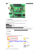
¾ Simple Examples in Arduino 328
These examples are designed to demonstrate how to use the modules with the Arduino. The Arduino's
hardware serial port is not used to connect to our modules, which keeps it available to the USB port. That
allows downloading new programs without having to continually disconnect/reconnect things. Most of
these examples use the LCD03 display module to show the results, but it is also possible to display the
results on the PC, as demonstrated in the CMPS03 example. All the modules which use the I2C bus
have 1k8 pull-up resistors to 5v. You only need one set of resistors, located near the Arduino, regardless
of however many I2C devices you have connected to it.
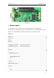
¾ LED control
Most Arduino boards already have an LED attached to pin 13 on the board itself. If you run this example
with no hardware attached, you could see LED blinks.This example shows the simplest thing you can do
with an Arduino to see physical output: it blinks an LED.
Sample code
/*
Blink
Turns on an LED on for one second, then off for one second, repeatedly.
This example code is in the public domain.
*/
void setup() {
// initialize the digital pin as an output.Pin 13 has an LED connected on most Arduino boards:
pinMode(13, OUTPUT);
}
void loop() {
digitalWrite(13, HIGH); // set the LED on
delay(1000); // wait for a second
digitalWrite(13, LOW); // set the LED off
delay(1000); // wait for a second
}