
Manual

www.nexusrobot.com Robot Kits manual
13
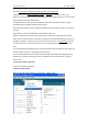
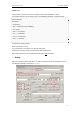
If your chip isn’t the same ,Some of the blank’s setting is different .change it base on the following chips :
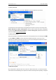
¾ Testing and confirming
- Disconnect a USB cable from Diecimila.
- Remove the wires of ICSP and X3.
- Connect a USB cable to Diecimila.
- Push the reset button of Diecimila.
- Start Arduino-IDE.
- Upload sample sketch “Blink”.
- And it will be run
See: http://www.roboticfan.com/article/html/797.shtml
or http://www.geocities.jp/arduino_diecimila/bootloader/index_en.html
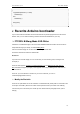
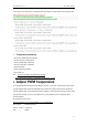
¾ Adjust PWM frequencies
The ATmega328P has three timers known as Timer 0, Timer 1, and Timer 2. Each timer has two output
compare registers that control the PWM width for the timer's two outputs: when the timer reaches the
compare register value, the corresponding output is toggled. The two outputs for each timer will normally
have the same frequency, but can have different duty cycles (depending on the respective output
compare register).
By macegr in this forum post
http://www.arduino.cc/cgi-bin/yabb2/YaBB.pl?num=1235060559/12
Pins 5 and 6: controlled by timer 0
Setting Divisor Frequency
0x01 1 62500