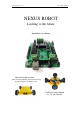
www.nexusrobot.com Robot Kits manual NEXUS ROBOT Looking to the future Robot Kits User’s Manual Nexus Automation Limited ADDR: 2/F,Chengxi Building. 819 S358 Road.
www.nexusrobot.com Robot Kits manual Nexus Robot A. Attention!! Please read this manual carefully before applying power on the device. B. Attention!! Do not use this device for military or medical purpose as they are not designed to. C. Attention!! Do not use over-voltage power supply ! ensure stable power supply. if there is high-voltage pulse, may cause the micro-control module permanent damage ! D.
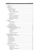
www.nexusrobot.com Robot Kits manual ¾ Arduino ...................................................................................................................1 ¾ Introduction......................................................................................................1 ¾ Hardware ...............................................................................................................1 ¾ Specification ........................................................................................
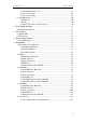
www.nexusrobot.com ¾ ¾ ¾ ¾ Robot Kits manual ¾ Communication Protocols.......................................................................27 ¾ Sensor Connection ..................................................................................29 ¾ Sensor Networking..................................................................................29 ¾ APC220 Module ............................................................................................30 ¾ Parameters................................
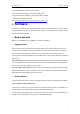
www.nexusrobot.com Robot Kits manual ¾ Arduino ¾ Introduction Arduino Controller is an All-in-One microcontroller especially designed for robotics application. Benefit from Arduino open source platform, it is supported by thousands of open source codes, and can be easily expanded with most Arduino Shields.Arduino can sense the environment by receiving input from a variety of sensors and can affect its surroundings by controlling lights, motors, and other actuators.
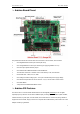
www.nexusrobot.com Robot Kits manual ¾ Arduino Board Pinout The picture above shows all of the I/O lines and Connectors on the controller, which includes: One Regulated Motor Power Input Terminal (6v to12v) One Unregulated Servo Power Input Terminal (you supply regulated 4v to 7.
www.nexusrobot.com Robot Kits manual ¾ Memory function The ATmega328 has 32 KB (with 0.5 KB used for the bootloader). It also has 2 KB of SRAM and 1 KB of EEPROM (which can be read and written with the EEPROM library). ¾ Input and Output PinMode Each of the 14 digital pins on the Duemilanove can be used as an input or output, using pinMode(), digitalWrite(), and digitalRead() functions. They operate at 5 volts.
www.nexusrobot.com Robot Kits manual When the Servo Power Select Jumper is applied, the servo is powered by internal 5V. When the Servo Power Select Jumper is not applied, the servo is powered by external power source. ¾ Motor Control Pin Jumper Applying the Motor Control Pin Jumpers will allocate Pin 4,5,6,7 for motor control. Removing the jumpers will release the above Pins.
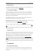
www.nexusrobot.com Robot Kits manual 4. Supporting Bluetooth module, APC220 module; 5. Auto Switch between external and onboard power supply; 6. Supporting SD card (read&write - our SD card module is needed); 7. Supporting IIC/I2C/TWI connection See: http://www.nexusrobot.com/product.php?id_product=51 ¾ Software The open-source Arduino environment makes it easy to write code and upload it to the i/o board. It runs on Windows, Mac OS X, and Linux.
www.nexusrobot.com Robot Kits manual 2 | Download the Arduino environment Get the latest version from the download page. When the download finishes, unzip the downloaded file. Make sure to preserve the folder structure. Double-click the folder to open it. There should be a few files and sub-folders inside. 3 | Connect the board The Arduino Uno, Mega, Duemilanove and Arduino Nano automatically draw power from either the USB connection to the computer or an external power supply.
www.nexusrobot.com Robot Kits manual See also: step-by-step screenshots for installing the Uno under Windows XP. Installing drivers for the Arduino Duemilanove, Nano, or Diecimila with Windows7, Vista, or XP: When you connect the board, Windows should initiate the driver installation process (if you haven't used the computer with an Arduino board before). On Windows Vista, the driver should be automatically downloaded and installed.
www.nexusrobot.com Robot Kits manual 7 | Select your board You'll need to select the entry in the Tools > Board menu that corresponds to your Arduino. For Duemilanove Arduino boards with an ATmega328 (check the text on the chip on the board), select Arduino Duemilanove or Nano w/ ATmega328. Previously, Arduino boards came with an ATmega168; for those, select Arduino Diecimila, Duemilanove, or Nano w/ ATmega168. (Details of the board menu entries are available on the environment page.
www.nexusrobot.com Robot Kits manual in the status bar. (Note: If you have an Arduino Mini, NG, or other board, you'll need to physically present the reset button on the board immediately before pressing the upload button.) A few seconds after the upload finishes, you should see the pin 13 (L) LED on the board start to blink (in orange). If it does, congratulations! You've gotten Arduino up-and-running. If you have problems, please see the troubleshooting suggestions.
www.nexusrobot.com Robot Kits manual { if (digitalRead(buttonPin) == HIGH) serialWrite('H'); else serialWrite('L'); delay(1000); } ¾ Re-write Arduino bootloader If you couldn't load the bootloader via the Arduino IDE with the parallel programmer from the Arduino website. Then you can used the following method to Re-write the bootloader on your chip. ¾ FT232RL BitBang Mode AVR-Writer FT232RL is an USB-Serial bridge on an Arduino Dicimila/NG/Duemilanove PCB.
www.nexusrobot.com ¾ Robot Kits manual Downloading To downloading the "avrdude-serjtag" FTDI BitBang AVR-Writer from the internet. configure-file for avrdude-serjtag avrdude.conf (Update: included chip-parameter of ATmega328P and 88P) avrdude-GUI-1.0.5.zip mirror site avrdude-GUI-1.0.5.zip original site (http://yuki-lab.jp/hw/avrdude-GUI/index.html)avrdude-GUI-1.0.5.zip mirror site avrdude-GUI (yuki-lab.jp Version) require Microsoft .NET Framework 2.0. When .NET Framework 2.0 is not installed.
www.nexusrobot.com Robot Kits manual avrdude.conf Copy(overwrite) "avrdude.conf" into the "C:\Program Files\avrdude-serjtag\binary" folder. This modified "avrdude.conf" has setting-scripts of "FTDI BitBang AVR-Writer" for Diecimila below. #arduino diecimila Programmer id="diecimila"; desc = "FT232R Synchronous BitBang"; type = ft245r; miso = 3; # CTS X3(1) sck = 5; # DSR X3(2) mosi = 6; # DCD X3(3) reset = 7; # RI X3(4) ; avrdude-GUI (yuki-lab.jp Version) Extract avrdude-GUI-1.0.5.zip.
www.nexusrobot.com Robot Kits manual If your chip isn’t the same ,Some of the blank’s setting is different .change it base on the following chips : ¾ Testing and confirming - Disconnect a USB cable from Diecimila. - Remove the wires of ICSP and X3. - Connect a USB cable to Diecimila. - Push the reset button of Diecimila. - Start Arduino-IDE. - Upload sample sketch “Blink”. - And it will be run See: http://www.roboticfan.com/article/html/797.shtml or http://www.geocities.
www.nexusrobot.com Robot Kits manual 0x02 8 7812.5 0x03 64 976.5625 0x04 256 244.140625 0x05 1024 61.03515625 TCCR0B = TCCR0B & 0b11111000 | ; Pins 9 and 10: controlled by timer 1 Setting Divisor Frequency 0x01 1 31250 0x02 8 3906.25 0x03 64 488.28125 0x04 256 122.0703125 0x05 1024 30.517578125 TCCR1B = TCCR1B & 0b11111000 | ; Pins 11 and 3: controlled by timer 2 Setting Divisor Frequency 0x01 1 31250 0x02 8 3906.25 0x03 32 976.
www.nexusrobot.com Robot Kits manual 0x05: delay(62) or 62 millis() ~ 1 second (Or 63 if you need to round up. The number is actually 62.5) Also, the default settings for the other timers are: TCCR1B: 0x03 TCCR2B: 0x04 There may be other side effects from changing TCCR0B. For example my project would not properly run with TCCR0B set to 0x02 or 0x01. But it worked fine at 0x03 and higher. ¾ Simple Examples in Arduino 328 These examples are designed to demonstrate how to use the modules with the Arduino.
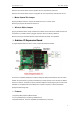
www.nexusrobot.com Robot Kits manual Led control ¾ Button module The controller has 7 build-in buttons S1-S7. S1-S5 use analog input, S6, S7 use digital input. To enable S6 and S7, please apply the jumpers indicated in the red circle. S6 uses Digital Pin2, S7 uses Digital Pin3. Once these enable jumpers have been applied, Pin 2 and 3 will be occupied.
www.nexusrobot.com digitalWrite(ledPin, LOW); Robot Kits manual // Set a low value to the ledPin } } Arduino button ¾ Interrrupt control Description Specifies a function to call when an external interrupt occurs. Replaces any previous function that was attached to the interrupt. Most Arduino boards have two external interrupts: numbers 0 (on digital pin 2) and 1 (on digital pin 3). The Arduino Mega has an additional four: numbers 2 (pin 21), 3 (pin 20), 4 (pin 19), and 5 (pin 18).
www.nexusrobot.com Robot Kits manual ¾ Digital Read Serial Fall Detector Example This example shows you how to monitor the state of a Fall detector by establishing serial communication between your Arduino and your computer over USB. Sample code const int PIN = 12; //set pin 12 as the signal pin void setup() { Serial.begin(9600); pinMode(PIN,INPUT); //set mode } void loop() { bool val = 0; val = digitalRead(PIN); //read pin 12 Serial.
www.nexusrobot.com Robot Kits manual Select the display Baud Rate ¾ Analog Read Serial Sharp 2D12 Example This example shows you how to read analog input, which from the physical world using a Sharp 2D12. A Sharp 2D12 is a simple mechanical device that provides a varying amount of resistance when its shaft is turned.
www.nexusrobot.com Robot Kits manual you need to drive more than one or two, you'll probably need to power them from a separate supply (i.e. not the +5V pin on your Arduino). Be sure to connect the grounds of the Arduino and external power supply together. As mentioned earlier, most servos expect a pulse width between 1-2 ms, however, a range of 0.5 ms to 2.5 ms (500-2500μs) may be required, depending on your servo. Experiment as necessary. Hi-Tec Servo Motors have three wires coming out of them.
www.nexusrobot.com Robot Kits manual ¾ Motor Control Hardware Setting Connect four motor wires to Motor Terminal. And apply power through motor power terminal. The PWM DC motor control is implemented by manipulating two digital IO pins and two PWM pins. As illustrated in the diagram above, Pin 4,7 are motor direction control pins, Pin 5,6 are motor speed control pins.
www.nexusrobot.com Robot Kits manual analogWrite(E1,100); TCCR2B = TCCR2B & 0b11111000 | 0x01; //set the timer1 as the work intrrupt timer // to use the timer will defualt at the function of setup; } void loop() { } The Motor sample to link wries ¾ Serial Port This example shows you how to monitor the state of a switch by establishing serial communication between your Arduino and your computer over USB. Sample code /* DigitalReadSerial .
www.nexusrobot.com Robot Kits manual void loop() { incomingByte = ((10485/(analogRead(ISRpin[0])+5))-4); //read the data from signal pin Serial.println(incomingByte,DEC); // display delay(500); } ¾ External device modules ¾ Dual Ultrasonic Sensor (DUS) ¾ Introduction DUS is based on RS485 interface. It allows a number of sensors working together. Up to 32 units may be connected together in a RS485 network.
www.nexusrobot.
www.nexusrobot.com Robot Kits manual ¾ RS485 Bus ¾ Introduction to RS485 RS485 are serial communication methods for computers and devices. RS485 bus advances in simpler cabling,longer transmitting distance and higher dependability. RS485 is the most versatile communication standard in the standard series defined by the EIA, as it performs well on all four points.
www.nexusrobot.com ¾ Robot Kits manual Network topology with RS485 RS485 is the only of the interfaces capable of internetworking multiple transmitters and receivers in the same network. When using the default RS485 receivers with an input resistance of 12 kΩ it is possible to connect 32 devices to the network. Currently available high-resistance RS485 inputs allow this number to be expanded to 256.
www.nexusrobot.com Robot Kits manual ¾ Communication Protocols The device is fixed at 19200 bps Baud Rate,8/N/1. Set Device Address Command: Header 55 Address Length Cmd Set Address SUM AB 1 55 ADD SUM Address Length Cmd Flag SUM ADD 1 55 S SUM Aa Return Value: Header 55 Aa PS: All connected SONAR will be changed to the given address. The new address must be between 0x11 and 0x30. If the address is set successfully, the flag will be set to 0x01 in the return data.
www.nexusrobot.com Robot Kits manual Read Distance Command: Header Address 55 aa ADD Header Address 55 Length Cmd aa 0 02 SUM Length Cmd ADD 2 SUM High Byte Low Byte 02 H L SUM SUM PS: The command will return the measured distance value. The value consists of two bytes. If the measurement is out of range or unsuccessful, the return data will be “0xFF(H) 0xFF(L)”.
www.nexusrobot.com Robot Kits manual Simple code: #include //used the library of SONAR // The sonar whose address is 0x11 was named S11, and it was setted as the type of SONAR SONAR s11=SONAR(0x11); //SONAR s12(0x12); void setup() { SONAR::init(); //set up some parameters delay(100); s11.setAddr(0x11); //100 millissecond //set address for S11with 0x11 . } //Ttrigger sonar and display the data. void loop() { s11.trigger(); //Send the trigger command to trigger S11 //s12.
www.nexusrobot.com Robot Kits manual ¾ APC220 Module ¾ Parameters Transmission Distance : 800m to 1200m Arduino Wireless Transmission APC220 PC Kits-1 based on APC220 ¾ Kit list 1. one APC220 Wireless Transmission module 2. one APC220 USB adaptation shield 3. one antenna ¾ This module used to connect PC port. How to use the RF module to control Arduino wirelessly? Its principle is similar to a remote control, which has 4 buttons for RF wireless remote control.
www.nexusrobot.com Robot Kits manual ¾ Pin Change Interrupt ¾ PinChangeInt Library This library was inspired by and derived from the PcInt example by "johnboiles", and written by a "jbrisbin" (it seems). While the PCInt example shows with generality how Pin Change interrupts can be done under Arduino, it is an 'example' effort that sacrifices performance for clarity of implementation. The PinChangeInt effort runs in the other direction, with clarity sacrificed for the highest performance.
www.nexusrobot.com Robot Kits manual 7. 8. #define PIN 15 // the pin we are interested in 9. byte burp=0; 10. byte cmd=0; // a counter to see how many times the pin has changed // a place to put our serial data 11. void setup() { 12. Serial.begin(9600); 13. Serial.print("PinChangeInt test on pin "); 14. Serial.print(PIN); 15. Serial.println(); 16. pinMode(PIN, INPUT); 17. digitalWrite(PIN, HIGH); //use the internal pullup resistor 18.
www.nexusrobot.com Robot Kits manual ¾ PID Control ¾ What Is PID From Wikipedia: "A PID controller calculates an 'error' value as the difference between a measured [Input] and a desired setpoint. The controller attempts to minimize the error by adjusting [an Output]." So, you tell the PID what to measure (the "Input",) Where you want that measurement to be (the "Setpoint",) and the variable to adjust that can make that happen (the "Output".
www.nexusrobot.com Input = analogRead(0); Robot Kits manual //initialize the variables we're linked to Setpoint = 100; myPID.SetMode(AUTOMATIC); //turn the PID on } void loop() { Input = analogRead(0); myPID.Compute(); analogWrite(3,Output); } See: http://www.arduino.cc/playground/Code/PIDLibrary ¾ Servo control Theory RC servos are comprised of a DC motor mechanically linked to a potentiometer.
www.nexusrobot.com Robot Kits manual ¾ The PWM signal In a nutshell, PWM is a way of digitally encoding analog signal levels. Through the use of high-resolution counters, the duty cycle of a square wave is modulated to encode a specific analog signal level. The PWM signal is still digital because, at any given instant of time, the full DC supply is either fully on or fully off. The voltage or current source is supplied to the analog load by means of a repeating series of on and off pulses.
www.nexusrobot.com Robot Kits manual ¾ Motorwheel This page describes how to control the built-in Motorwheel. ¾ Motorwheel Class Reference This document describes how to use the Motor library to control Motors. On the Introduction, you will know how to controls the motor’s PWM, direction and speed . This motorwheel library version 1.1,compatible with maple.
www.nexusrobot.com Robot Kits manual ¾ Class Motor Reference This section gives a full listing of the capabilities of a Motor. Class Motor : public PID Interface for visit of peripherals . Inherit from the Public PID. ¾ Public functions Motor(unsigned char _pinPWM,unsigned char _pinDir, unsigned char _pinIRQ,unsigned char _pinIRQB, struct ISRVars* _isr) Construct a new Motor instance. In your sketch. This will create a Motor object called Motor.
www.nexusrobot.com Return: Robot Kits manual Direction pin unsigned char getPinIRQ() const Get the IRQ Pin number Return: IRQ pin unsigned char getPinIRQB() const Get the IRQB Pin number Return: IRQB pin unsigned int runPWM(unsigned int PWM,bool dir,bool saveDir=true); Set the PWM and direction for Motors .then return the PWM.
www.nexusrobot.
www.nexusrobot.
www.nexusrobot.
www.nexusrobot.com Robot Kits manual According to the User’s demands ,use the class PID to set the speed of Motor.
www.nexusrobot.com Robot Kits manual Define a Pointer named isr, as the member of the struct ISRVars ¾ Private members unsigned char pinPWM The PWM pin. unsigned char pinDir The diretion pin unsigned char pinIRQ The IRQ pin unsigned char pinIRQB The IRQB pin bool desiredDirection The desired direction unsigned int speedPWM Save the current PWM int speedRPMInput Save the Motor’s current speed.it will be used in class PID int speedRPMOutput Save the speed of the Motor output.
www.nexusrobot.com Robot Kits manual unsigned char _pinIRQ,unsigned char _pinIRQB, struct ISRVars* _isr, unsigned int _ratio=REDUCTION_RATIO); Construct a new GearedMotor instance. In your sketch. This will create a GearedMotor object called GearedMotor.
www.nexusrobot.
www.nexusrobot.
www.nexusrobot.com Robot Kits manual unsigned int getSpeedMMPS() const Get the speed (millimeter per second) This will lie within the range specified at MotorWheel::getspeedCMPM(). See: MotorWheel::getspeedCMPM() unsigned int setSpeedMMPS(unsigned int mm,bool dir) Set the speed . This will lie within the range specified at MotorWheel::setspeedCMPM() and MotorWheel::getspeedCMPM(). MotorWheel::setspeedCMPM() See: MotorWheel::getspeedCMPM() For example: #include
www.nexusrobot.com Robot Kits manual Serial.println(wheel1.getSpeedRPM(),DEC); Serial.print("MMPS //display the speed of the MotorWheel --> "); Serial.println(wheel1.getSpeedMMPS(),DEC); //display the speed of the motor //wheel1.
www.nexusrobot.com Robot Kits manual ¾ R2WD This page describes how to control the built-in R2WD. It does not describe how the R2WD work on your board. For more information on that, please refer to R2WD Class Reference.
www.nexusrobot.com Robot Kits manual In your sketch. This will create a R2WD object called R2WD.
www.nexusrobot.
www.nexusrobot.
www.nexusrobot.
www.nexusrobot.
www.nexusrobot.
www.nexusrobot.
www.nexusrobot.
www.nexusrobot.
www.nexusrobot.com Robot Kits manual Float taui Integral term Float taud Derivative term Unsigded int interval The time the PID work last see : MotorWheel::PIDEnable() bool PIDRegulate() Regulate the PID ,in order to adjust the speed of the Motor.
www.nexusrobot.
www.nexusrobot.com Robot Kits manual void debugger(bool wheelLeftDebug=true,bool wheelRightDebug=true) const; Debug the all wheel’s speed Car _state enum Used to configure the behavior of a car. Note that not all car can be configured in every state.
www.nexusrobot.com Robot Kits manual Motor _state enum Used to configure the behavior of a motor. Note that not all motors can be configured in every state. Variables: MOTORS_FB The switchmotorstat is FB MOTORS_BF The switchmotorstat is BF unsigned char getSwitchMotorsStat() const Get the state of the Motor return : The motor’s state unsigned int getRadiusMM() const Get the radius the car moves If the car state was rotateleft or rotateright.
www.nexusrobot.
www.nexusrobot.
www.nexusrobot.
www.nexusrobot.
www.nexusrobot.
www.nexusrobot.com Robot Kits manual setCarSpeedMMPSArc(speedMMPS,getRadiusMM(),uptime); } delayMS(duration,debug); //duration=5000 the car moves this action willl last 5000 milliseconds setCarSlow2Stop(uptime); //uptime=500 set the car stop in 500 milliseconds } } ¾ R2WD_test Here’s an example ,we use it to test a car with two wheels.after this ,you will More thorough understanding of the library Simple code: #include #include #include #include
www.nexusrobot.com Robot Kits manual MotorWheel wheel2(10,11,6,7,&irq2,REDUCTION_RATIO,int(144*PI)); R2WD _2WD(&wheel1,&wheel2,WHEELSPAN); // This will create a R2WD object called R2WD. You // can then use any of its methods; for instance, to // control a R2WD attached to pins, you could write void setup() { //TCCR0B=TCCR0B&0xf8|0x01; // warning!! it will change millis() TCCR1B=TCCR1B&0xf8|0x01; // Pin9,Pin10 PWM 31250Hz //TCCR2B=TCCR2B&0xf8|0x01; // Pin3,Pin11 PWM 31250Hz _2WD.PIDEnable(0.26,0.
www.nexusrobot.com Robot Kits manual Sample Wiring Diagram for RB004 2WD V2.
www.nexusrobot.com Robot Kits manual ¾ 2WD platform with 3 SONAR Look the above figure of simple Wiring Diagram for RB004 2WD V2.0. this code is matched for it RB004_2WD_PID_3SONAR_3IR code #include #include #include #include #include #include #include #include
www.nexusrobot.
www.nexusrobot.com Robot Kits manual /* void loop() { _2WD.
www.nexusrobot.com Robot Kits manual Omni Wheel Robots employing omni wheel are capable of moving in any direction by changing velocity and direction of each wheel without changing its orientation.As there are small rollers around the circumference of omni wheels which are perpendicular to the rolling direction making them capable of sliding laterally. Omni wheel Mecanum wheel Mecanum wheel is a conventional wheel with a series of rollers attached to its circumference.
www.nexusrobot.
www.nexusrobot.com Robot Kits manual ¾ Public functions Omni3WD (MotorWheel* wheelBack,MotorWheel* wheelRight,MotorWheel* wheelLeft) Construct a new Omni3WD instance. in your sketch. This will create a Omni3WD object called Omni3WD.
www.nexusrobot.com Robot Kits manual The speed for the motor to run,initialize it.
www.nexusrobot.com Robot Kits manual Set the car moves forward Because the car have three wheels ,so the car moves forward ,the wheels will have different state. This will lie within the range specified at Omni3WD::setCarstat() and Omni3WD::wheelBackSetSpeedMMPS() and Omni3WD::wheelRightSetSpeedMMPS() and Omni3WD::wheelLeftSetSpeedMMPS() unsigned int speedMMPS=0 Parameters: The speed for the car moves,initialize it.
www.nexusrobot.com Robot Kits manual Omni3WD::wheelBackSetSpeedMMPS() Omni3WD::wheelRightSetSpeedMMPS() Omni3WD::wheelLeftSetSpeedMMPS() unsigned int setCarRight(unsigned int speedMMPS=0) Set the car turn right This will lie within the range specified at Omni3WD::setCarstat() and Omni3WD::wheelBackSetSpeedMMPS() and Omni3WD::wheelRightSetSpeedMMPS() and Omni3WD::wheelLeftSetSpeedMMPS() unsigned int speedMMPS=0 Parameters: The speed for the car moves,initialize it.
www.nexusrobot.com Robot Kits manual unsigned int getCarSpeedMMPS() const Get the car’s speed return: The car’s speed unsigned int setCarSpeedMMPS(unsigned int speedMMPS=0,unsigned int ms=1000) The car’s speed be set This will lie within the range specified at Omni3WD::getCarSpeedMMPS() unsigned int speedMMPS=0 The speed for the car moves,initialize it.
www.nexusrobot.
www.nexusrobot.com Robot Kits manual Float kc Proportional term,initialize it Float taui Integral term Parameters: Float taud Derivative term Unsigded int interval The time the PID work last see : MotorWheel::PIDEnable() bool PIDRegulate() Regulate the PID ,in order to adjust the speed of the Motor.
www.nexusrobot.com Robot Kits manual STAT_STOP The car’s state is stop STAT_ADVANCE The car’s state is moves forward STAT_BACKOFF The car’s state is get backoff STAT_ROTATELEFT The car’s state is moves rotate left STAT_ROTATERIGHT The car’s state is moves rotate right STAT_RIGHT The car’s state is turn right STAT_LEFT The car’s state is turn left unsigned char getCarStat() const Get the state of the car return : The car’s state Motor _state enum Used to configure the behavior of a motor.
www.nexusrobot.
www.nexusrobot.
www.nexusrobot.com Robot Kits manual ¾ Omni3WD_test Here’s an example ,we use it to test a car with three wheels.after this ,you will More thorough understanding of the library Simple code: #include #include #include #include #include #include // Include the header files /* Wheel3 // \\ Wheel2 == Wheel1 */ irqISR(irq1,isr1); // Intterrupt function.
www.nexusrobot.com Robot Kits manual // to control a Omni3WD attached to pins, you could write void setup() { TCCR1B=TCCR1B&0xf8|0x01; // Timer1.Pin9,Pin10 PWM 31250Hz TCCR2B=TCCR2B&0xf8|0x01; // Timer2 .Pin3,Pin11 PWM 31250Hz Omni.PIDEnable(0.26,0.02,0,10); // Enable PID } void loop() { Omni.demoActions(100,5000,1000,false); //Call the demoActions speedMMPS=100 duration=5000 uptime =1000. /* Omni.setCarLeft(0); Omni.setCarSpeedMMPS(300,1000); Omni.delayMS(10000,true); Omni.
www.nexusrobot.com Robot Kits manual Diagram for Omni3WD_V1.
www.nexusrobot.com Robot Kits manual ¾ Omni3WD platform with 3 SONARS Look the above figure of simple Wiring Diagram for Omni3WD_V1.0. Tis code is matched for it Diagram_Omni3WD_V1.0 code /********************************************************************/ /* Power Switch Sonar0x11 ------------------------/ \ / \ / M3 \ / \ M2 INT0 / \INT1 / \ / \ / \ \ / \ / \ / \ Sonar0x12 / \ / Sonar0x13 \ / \ / -------------------------M1 */ #include #include
www.nexusrobot.com Robot Kits manual SONAR sonar11(0x11),sonar12(0x12),sonar13(0x13); // Software initialization //SONAR is be defined in as a class unsigned short distBuf[3]; // Used to save the data of the 3 sonars return; void sonarsUpdate() { //the function to static unsigned char sonarCurr=1; // A variable save a data used to flag the current of sonar if(sonarCurr==3) sonarCurr=1; else ++sonarCurr; if(sonarCurr==1) { // The conditions is ture? distBuf[1]=sonar12.
www.nexusrobot.com Robot Kits manual /******************************************/ // demo unsigned long currMillis=0; void demoWithSensors(unsigned int speedMMPS,unsigned int distance) { if(millis()-currMillis>SONAR::duration) { // every 60ms call sonarUpdate once currMillis=millis(); sonarsUpdate(); } if(distBuf[1]
www.nexusrobot.com Robot Kits manual Diagram_Omni3WD_V3.
www.nexusrobot.com Robot Kits manual ¾ Omni3WD platform with 6 SONARS Look the above figure of simple Wiring Diagram for Omni3WD_V3.3. Tis code is matched for it Diagram_Omni3WD_V3.
www.nexusrobot.com Robot Kits manual SONAR sonar11(0x11),sonar12(0x12),sonar13(0x13),sonar14(0x14),sonar15(0x15),sonar16(0x16); // Software initialization //SONAR is be defined in
www.nexusrobot.com void checkIRs() { Robot Kits manual // Read the Anti-drop Sonars for(int i=0;i<3;++i) { IRs[i]=digitalRead(IRpin[i]); // Save datas Serial.print(IRs[i]); // display the datas } Serial.
www.nexusrobot.com Robot Kits manual if(IRs[1] || IRs[2]) { // The Anti-drop return a High Value Omni.setCarBackoff(speedMMPS); Omni.delayMS(ms); // get car back // delay “ms” ,every 10 ms call the PIDregulate() once time. if(IRs[1]) { Omni.setCarRotateLeft(speedMMPS); } else Omni.setCarRotateRight(speedMMPS); Omni.delayMS(ms); } else if(distBuf[1]
www.nexusrobot.com Robot Kits manual ¾ Omni4WD This page describes how to control the built-in Omni4WD. It does not describe how the Omni4WD work on your board. For more information on that, Please refer to Omni4WD Class Reference.
www.nexusrobot.com Robot Kits manual ¾ Omni4WD Class Reference This document describes a car with four Motors. On the Introduction, you will know how to use the Omni4WD library to control the Motors,then to control the car #include Include the header file MotorWheel.
www.nexusrobot.com See: Robot Kits manual Omni3WD::getSwitchMotorsStat() unsigned char switchMotorsReset() Reset for switch motors to control unsigned int setMotorAll(unsigned int speedMMPS=0,bool dir=DIR_ADVANCE) Set all motors’ speed and direction This will lie within the range specified at Omni4WD:: wheelULSetSpeedMMPS() and Omni4WD::wheelLLSetSpeedMMPS() and Omni4WD::wheelLRSetSpeedMMPS() and Omni4WD::wheelURSetSpeedMMPS() unsigned int speedMMPS=0 The speed for the motor run,initialize it.
www.nexusrobot.com Robot Kits manual This will lie within the range specified at Omni4WD::setMotorAll() unsigned int speedMMPS=0 Parameters: The speed for the motor run,initialize it.
www.nexusrobot.com Robot Kits manual unsigned int speedMMPS=0 Parameters: The speed for the motor run,initialize it.
www.nexusrobot.com Robot Kits manual Omni4WD::setCarstat() unsigned int setCarRotateLeft(unsigned int speedMMPS=0) Set the car rotate left This will lie within the range specified at Omni4WD::setCarstat() and mni4WD::setMotorAllBackoff() unsigned int speedMMPS=0 Parameters: The speed for the car moves,initialize it.
www.nexusrobot.com Robot Kits manual unsigned int setCarLowerLeft(unsigned int speedMMPS=0) Set the car Lower left This will lie within the range specified at Omni4WD::wheelULSetSpeedMMPS() and Omni4WD::wheelLLSetSpeedMMPS() and Omni4WD::wheelLRSetSpeedMMPS() and Omni4WD::wheelURSetSpeedMMPS() and Omni4WD::setCarstat() unsigned int speedMMPS=0 Parameters: The speed for the motor run,initialize it.
www.nexusrobot.com Robot Kits manual The speed for the motor run,initialize it.
www.nexusrobot.com Robot Kits manual This will lie within the range specified at Omni4WD::getCarSpeedMMPS() unsigned int speedMMPS=0 The speed for the car moves,initialize it.
www.nexusrobot.
www.nexusrobot.com Robot Kits manual The speed for the wheel run,initialize it bool dir=DIR_ADVANCE The direction for the wheel run See: MotorWheel::setSpeedMMPS() bool PIDEnable(float kc=KC,float taui=TAUI,float taud=TAUD,unsigned int interval=1000) Call the PID,make it work for the car.
www.nexusrobot.com Robot Kits manual void debugger(bool wheelBackDebug=true,bool wheelRightDebug=true,bool wheelLeftDebug=true) const Debug the speed of the wheel Car _state enum Used to configure the behavior of a car. Note that not all car can be configured in every state.
www.nexusrobot.com Robot Kits manual unsigned char getCarStat() const Get the state of the car return : The car’s state Motor _state enum Used to configure the behavior of a motor. Note that not all motors can be configured in every state.
www.nexusrobot.com Robot Kits manual Carstate if the stat in the range of the want return : STAT_UNKNOWN otherwise unsigned char _switchMotorsStat Switch the motors’ state unsigned char setSwitchMotorsStat(unsigned char switchMotorsStat) Set the Motors’ state This will lie within the range specified at Omni4WD::getSwitchMotorsStat() Parameters: unsigned char switchMotorsStat The state want to set See: Omni4WD::getSwitchMotorsStat() Omni4WD() Construct a new R2DW instance.
www.nexusrobot.
www.nexusrobot.com Robot Kits manual ¾ Omni4WD_test Here’s an example ,we use it to test a car with four wheels.after this ,you will More thorough understanding of the library Simple code: #include #include #include #include #include #include // Include the header files /* \ / wheel1 \ Left / \ wheel4 / / Right \ wheel2 / \ Right / wheel3 \ Left */ irqISR(irq1,isr1); // Intterrupt function.
www.nexusrobot.com Robot Kits manual MotorWheel wheel3(9,8,16,17,&irq3); irqISR(irq4,isr4); MotorWheel wheel4(10,7,18,19,&irq4); Omni4WD Omni(&wheel1,&wheel2,&wheel3,&wheel4); // This will create a Omni4WD object called Omni4WD.
www.nexusrobot.com Robot Kits manual Sample Wiring Diagram for RB011 ,Mecanum 4WD V4.
www.nexusrobot.com Robot Kits manual ¾ 4WD platform with 4 SONAR Look the above figure of simple Wiring Diagram for RB011 ,Mecanum 4WD V4.1. this code is matched for it 4WD platform with 4 SONAR code #include #include #include #include #include #include
www.nexusrobot.com Robot Kits manual irqISR(irq4,isr4); MotorWheel wheel4(10,7,18,19,&irq4); Omni4WD Omni(&wheel1,&wheel2,&wheel3,&wheel4); // This will create a Omni4WD object called Omni. then You can use any of its methods; // for instance, to control a Omni4WD attached to pins, you could write SONAR sonar11(0x11),sonar12(0x12),sonar13(0x13),sonar14(0x14); // Software initialization //SONAR is be defined in
www.nexusrobot.com Robot Kits manual if(Omni.getCarStat()!=Omni4WD::STAT_LEFT) Omni.setCarSlow2Stop(300); Omni.setCarLeft(0); Omni.setCarSpeedMMPS(speedMMPS, 300); } void turnRight(unsigned int speedMMPS){ if(Omni.getCarStat()!=Omni4WD::STAT_RIGHT) Omni.setCarSlow2Stop(300); Omni.setCarRight(0); Omni.setCarSpeedMMPS(speedMMPS, 300); } void rotateRight(unsigned int speedMMPS){ if(Omni.getCarStat()!=Omni4WD::STAT_ROTATERIGHT) Omni.setCarSlow2Stop(300); Omni.setCarRotateRight(0); Omni.
www.nexusrobot.
www.nexusrobot.com Robot Kits manual This document describes a car with three servo Motors. On the Introduction, you will know how to control the servo Motors,then to control the car Before you read this code,you should know about the Servo Motor Theory.To understand how the motor works.
www.nexusrobot.
www.nexusrobot.com pinMode(MOTOR1_E, OUTPUT); Robot Kits manual // Define the pin Mode as OUTPUT pinMode(MOTOR2_E, OUTPUT); pinMode(MOTOR3_E, OUTPUT); Serial.
www.nexusrobot.com Robot Kits manual ¾ Servo_3WD platform with 3 SONAR Look the above figure of simple Wiring Diagram for 3WD omni wheel mobile robot. Tis code is matched for it Servo_3WD omni wheel mobile robot code #include // Include the header files SONAR sonar11(0x11),sonar12(0x12),sonar13(0x13); // Software initialization //SONAR is be defined in
www.nexusrobot.
www.nexusrobot.