Autopilot - Instrument - Installation and Operation Manual English English
AUTOPILOT 1
AUTOPILOT This manual is written for NX2 Autopilot version 2.01 – 2.
AUTOPILOT 1 2 3 4 5 6 Part specification.................................................................................................................... 6 1.1 Welcome aboard!............................................................................................................ 8 1.2 Capabilities ..................................................................................................................... 8 1.3 Principle of operation.....................................................
AUTOPILOT 6.3 Autopilot setup group [P] ...............................................................................................25 6.3.1 P0, Return [RET] ..................................................................................................25 6.3.2 P1, Rudder [RUD] ................................................................................................25 1.1.5 P2, Damping of compass heading [SEA] .............................................................26 6.3.
AUTOPILOT 11.4.1 Location of Servo Unit ......................................................................................... 49 11.4.2 Installing Servo Unit............................................................................................. 49 11.4.3 Connecting Servo Unit......................................................................................... 50 11.4.4 Safety switch........................................................................................................ 52 11.4.
AUTOPILOT 1 Part specification ___________________________________________________________ Items delivered with the instrument 1 1 5 5 4 4 1 1 1 2 1 1 1 1 1 1 1 NX2 Autopilot instrument Instrument cover Cable protectors, 0,25 mm (0.1 inch) Cable protectors, 0,75 mm (0.
AUTOPILOT 7
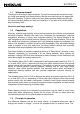
AUTOPILOT 1.1 Welcome aboard! Thank you for choosing a Nexus Autopilot. Through this manual we would like to help you install and operate your Nexus product. We are convinced that you will appreciate the useful functions. To get the most out of your Nexus product, please read through this manual carefully before you start your installation. If you see us at a show, please stop by and say hello. Good luck and happy boating! 1.
AUTOPILOT rudder is moved as necessary to return the boat back on course. The sensitivity to course errors andamount of correction are user adjustable to suit different boats under various sea conditions. NB * (PID control, terminology as known by control technicians, P = proportional part, I = integral part and D = derived part) Factory default settings and automatic calibration, establish a basis for normal steering and may be further fine tuned if necessary.
AUTOPILOT 1.1.2 Pumpset Various sizes and types of pumpsets can be mounted into a hydraulic steering system. The pumpset only operates when carrying out a rudder command. When the boat is on course, the pumpset motor stops. A variable speed motor drive adjusts optimal rudder speed and provides for minimum power consumption and maximising of rudder positioning accuracy. 1.1.3 Linear Drive A hydraulic linear drive is used to drive the tiller arm or quadrant of mechanical steering systems.
AUTOPILOT 2 • 1. 2. 3. 4. 5. 6. Installation The installation includes 6 major steps: Read the installation and operation manual. Plan where to install the transducers and instruments. Run the cables. Install the transducers and instruments. Take a break and admire your installation. Learn the functions and calibrate your system. Before you begin drilling ... think about how you can make the installation as neat and simple as your boat will allow.
AUTOPILOT 2.1 Installing the instrument • Place the adhesive drill template on the desired location for the instrument. Drill the 2 holes using a 5 mm (1/4") drill for the two pin bolts. Use a 63 mm (2½") hole saw to machine the clearance hole for the instrument connection socket. Remove the template.
AUTOPILOT • • Apply silicon paste to the instrument connection pins at the back of the instrument. Press the jack plug onto the instrument pins. Press the cable in to the cable leads. Mount the connection back cover with the screw. 2.1.1 Installing instrument to the Server All NX2 instruments are connected directly to the Nexus Network in a daisy chain. They all use the same colour coded 4-pole jack plugs. (For instrument installation, see 2.2).
AUTOPILOT 3 First start At each power on, the instrument will perform a self test. The display will first show all segments, then the software version and the Nexus Network ID number. 3.1 Initialising the instrument in a Nexus Network At the first power on after installation, you will be asked to press SET [PrSKEY]. This will give the instrument a logical ID number from 16 and upwards on the Nexus Network.
AUTOPILOT the instruments that had the same ID number, then re-install the instruments and repeat the above procedure.
AUTOPILOT 4 Operation 4.1 Instrument overview Top-line Heading Pagearrow Function Autopilot on Reference course / angle Lower -line function text SET OFF LEFT MODE RIGHT 4.1.1 Instrument display The display consists of two lines, a top-line with 24 mm (1”) digits and a lower-line with 13 mm (0.5”) digits. 4.1.2 Instrument pages and functions The Autopilot instrument has its functions divided into 4 pages.
AUTOPILOT 1.1.4 Instrument power on/off You will switch on/off your Nexus instruments by using the instrument switch on your electrical panel as the instruments have no separate power on/off-button. 4.2 How to use the push-buttons 4.2.1 MODE A press on MODE, moves one page to the right, indicated by the page-arrow at top of the display. In edit mode, a press on MODE moves the cursor one step to the right. It scrolls in a circular pattern, one step for every press. 4.2.
AUTOPILOT 4.2.7 Setup mode To access setup mode, press and hold MODE more than 2 seconds. [Lit OFF] flashes. To move to next setup group, press MODE again. To return to standby mode, press SET when the text return [RET] is displayed. 4.2.8 Lighting The instrument uses red back lighting for the display and the 4 push-buttons. The light can be set at 4 different levels. To access the light control, press and hold MODE for more than 2 seconds.
AUTOPILOT 5 Function 5.1 Standby mode At power on the Autopilot starts is in standby mode and operates as a passive compass repeater. No page-arrow is shown at the top of the display. The current course is displayed on the top-line. The rudder angle is displayed on the bottom line. In any function, the top-line displays the heading at all times. 5.
AUTOPILOT 5.2.4 Automatic steering by navigator Automatic steering by navigator is only possible if a navigator is connected and it is navigating towards a waypoint. To select steering by navigator, press MODE until the page-arrow appears under NAV, and [NAV] is flashing on the lower-line. Your present course is displayed on the top-line.
AUTOPILOT Note! The apparent wind speed must be more than 3 knots. If the apparent wind speed falls below 3 knots, wind signals are disabled and the Autopilot will maintain the current magnetic heading reference instead. Before activating wind steering, optimise your sail trim. To select wind steering, press MODE until the page-arrow appears under WIND, and Apparent Wind Angle [AWA] is flashing on the lower-line. Your present course is displayed on the top-line.
AUTOPILOT 5.2.6 Power steering To select power steering, press MODE until the page-arrow appears under PWR ST, and Rudder Angle Indicator [RAI] is flashing on the lower-line. Your present course is displayed on the top-line. To activate power steering, press SET when [RAI] is flashing. The rudder angle, followed by a sign for port or starboard is displayed on the lower-line. To change the rudder angle to starboard press RIGHT and hold it, until the desired rudder angle is displayed.
AUTOPILOT 6 Setup 6.1 Setup mode To get the most out of your Nexus product, it is important to carefully setup and calibrate your Network. The settings are stored in a non-volatile memory, which means they will remain in memory after you have turned off the power. To get an overview of your Network settings, we recommend that you note your settings. 6.1.1 [Lit OFF] [P0] - [P9] [A0] - [A4] [C0] - [C6] 6.1.
AUTOPILOT Note! The above explanation is only mentioned here. It is not repeated for each setup.
AUTOPILOT Caution! All setup routines can be adjusted while the boat is underway with Autopilot functions activated. Always be in a position to monitor the boat’s heading and to watch for navigational hazards when calibrating the Autopilot. Be prepared to turn off the Autopilot by a long press on OFF, to revert to manual steering immediately if an undesired heading occurs. If navigating with an automatic steering function in a hazardous situation, do not adjust setup routines while underway. 6.
AUTOPILOT 1.1.5 P2, Damping of compass heading [SEA] Possible settings are [0] = Minimum to [9] = Maximum. Set by the APC routine. This setting is a combination of yaw dead-band (compass sensitivity) and compass damping. The minimum setting may only be used under calm sea conditions to avoid unnecessary rudder correction due to compass acceleration errors. Smaller boats and high speed boats, which are subject to more acceleration in lighter seas will have to use higher settings.
AUTOPILOT Damping of wind transducer. The factory default setting should be adequate. In very heavy weather or unstable wind conditions, unnecessary corrections may be minimised by increasing the setting. 6.3.5 P5, Automatic Trim Calibration [ATC] Possible settings are [0] = Minimum to [9] = Maximum. Set by the APC routine. [ATC] is not critical. It constantly compares the course set against the course steered and slowly applies more rudder as necessary to reduce any errors to zero.
AUTOPILOT The [RRS] will be set to [5] after the APC routine is performed. It is then possible to increase or decrease the speed reduction of the pumpset motor. 6.3.9 P9, Rudder angle limit [LIM] Possible settings are [0°-99°]. Default setting is [00°]. An angle of 00° is the same as rudder angle limit disconnected (OFF). Note! Make sure [LIM] is set to 00° (OFF) during installation. The rudder angle limit sets maximum angle for the rudder.
AUTOPILOT If the pilot’s cross track error exceeds the set threshold of distance of the track, the alarm will be activated. 6.4.5 A4, Push-button beep [KEY] Possible settings are [OFF] or [On]. Default setting is [ON]. [On] = Sound when push buttons are pressed. [OFF] = No sound. 6.5 Compass setup group [C] Auto-deviation, auto-deviation-check and auto-deviation clear, are only available if a Nexus compass transducer is connected.
AUTOPILOT If successful, the text [CAL C3] [Auto DEV] will be displayed. If not, an error messages can be displayed: • [Err 15]: Make sure an Autopilot function is not activated and carry out the auto-deviation procedure again. • [Err 16]: Auto-Deviation is not possible, because a NMEA compass is selected as compass for the Nexus Network. • [Err 17]: The 1 ¼ turn was not performed or the compass is affected by strong magnetic distortion.
AUTOPILOT 6.5.7 C6, Adjust compass alignment [ADJ] Possible settings are [000°] to [359°]. Default setting is [000]. Compass transducer alignment correction or the so called, ”A-fault”. Allows 180° reversed mounting if needed. Never mount the transducer at right angles to the boats fore-aft line. Make sure that the local magnetic variation is entered before you make the alignment adjustment, otherwise you are unable to see the difference between local magnetic variation and alignment error.
AUTOPILOT 7 Maintenance 7.1 • • • • • Instrument maintenance To clean the instrument, use only mild soap solution and rinse with water. Do not use detergents or high pressure washing equipment. At least once a year, check all your connections and apply additional silicon paste at each connection point.
AUTOPILOT 8 Fault finding 8.1 General Before you contact your Nexus dealer and to assist your dealer to give you a better service, please check the following points and make a list of: • All connected instrument and transducers, including their software versions. • Nexus Network ID numbers for each instrument (displayed at power up). In most cases, the reason for faults in electronic equipment is poor installation.
AUTOPILOT Pumpset contamination Symptom Clean or replace pumpset Cause Action Blinking [Low Bat] on Low battery voltage. Automatic bottom line of display shut-off in case of voltage lower than 10.5 V (12 V battery) and 21.5 V (24 V battery). Poor wiring connection. Power wiring is undersized. When Autopilot APC routine not performed. engaged, rudder goes harddover. Power transistors in Servo Unit may be shorted. Rudder transmitter linkage disconnected. Rudder transmitter wiring shorted or open circuit.
AUTOPILOT Autopilot instrument is compass is not aligned with fordifferent from ship’s aft line of boat. steering compass. Variable error in heading caused by magnetic interference. alignment of compass. Verify that the steering compass is accurately corrected and then correct the Autopilot compass as per installation instructions. Large errors not corrected by 1. Run Auto-Deviation-Clear [C5] [CLR]. above remedies or lack of 2. Run Auto-Deviation [C3] [DEV] change in course set point with 3.
AUTOPILOT 8.3 Nexus Network error messages with cause and remedy If an error message [Err #] is displayed, an error has been detected by the Nexus Network. The message can assist you to diagnose the cause and remedy the error. To escape from an error message, press any push-button. If not possible to escape, reset power (turn off and on again), then make the remedy if suggested below. Note! For errors marked with [*], contact your national distributor to return the unit for rectification. No.
AUTOPILOT 23 24 DGPS (RTCM) data ignored. Change the DGPS (RTCM) setting. GPS bad fix, no fix position (time expired Check GPS antenna location. at one-fix). 25 No Autopilot response. Object is not connected. The unit is not allowed to power up because there is too high input voltage. Extended object server busy or error. 26 27 28 29 3041 42 30 31 32 33 34 35 36 37 41 Route command error. The waypoint bank memory is full. DGPS mode is interrupted. Reserved for Nexus Autopilot Servo Unit.
AUTOPILOT 9 Specifications 9.1 Technical Specifications 9.1.1 Autopilot instrument Dimensions: 113 x 113 x 23 mm (4.3 x 4.3 x 0.9”) Weight: 260 g (9.17 oz) Enclosure: Water proof Instrument cable: 0.4 m (16”) Power supply: 12 V DC (10-16 V). The instrument is polarity protected. Power consumption: 0,08 W. At max lighting 0.8 W. Current consumption: 7 mA (at 12V). At max lighting 70 mA (at 12V). 9.1.2 Servo Unit A-1500 Dimensions: 220 x 145 x 55 mm (8.7 x 5.7 x 2.2”) Weight: 800 g (28.
AUTOPILOT Temperature range: The above products have the same temperature range. Storage: -30°C to +80°C.( -22°F to 176°F) Operation: -10°C to +70°C. (14°F to 158°F) Warranty period: The above products have the same 2 year warranty period, see separate conditions. CE approval: The above products conforms to the EMC requirements for immunity and emission according to EN 5008-1 and EN 55022 9.
AUTOPILOT 9.3.3 Nexus analog Rudder Angle instrument The analog Rudder Angle instrument (Art. No. 20550-9) indicates the rudder angle (50° - 0 - 50°). This instrument is connected on the Nexus data bus cable as per colour codes. 9.3.4 Nexus Multi Control instrument with Server The Nexus Server is the heart of the Nexus Network to which transducers for speed, depth, wind, compass and navigators are connected.
AUTOPILOT 21735 Bracket for GPS Antenna and 35° Compass transducer for bulkhead mount 22117-1 22117-3 22117-4 22117-5 22117-6 22117-7 NX2 Digital Instruments (all supplied with 0.2m cable) Speed log instrument Multi Control instrument Wind Data instrument Compass Data instrument GPS Navigator instrument Autopilot instrument 22115-01 22115-02 22115-03 22115-05 22115-06 22115-07 22115-08 22115-09 22115-10 22115-11 22115-12 22115-13 NX2 Analog Instruments (all supplied with 0.
AUTOPILOT 21680-1 21684-1 69995 Nexus Multi XL Multi XL instrument, 4m cable (RCI or Multi Center needed to control Multi XL) Multi XL Set, Multi XL instrument and Remote Control instrument Mast bracket XL, in aluminium for Multi XL and Nexus / Star 110x110mm instr.
AUTOPILOT 9.4 Abbreviations Abbr.
AUTOPILOT KT KTS LCD LOW m m/s MAG MAX MEM MID MIN MN MOB N NAV NM NMEA OCA PCA PWR RAM RET RRS RUD S S/A SAT SEA SEC SOG STR tru USR VAR VER W WP XTE KnoTs KnoTS Liquid Crystal Display LOW metre metres per second Magnetic North MAX MEMory MID MINimum Magnetic North Man Over Board North NAVigate Nautical Mile National Marine Electronic Associat Off Course Alarm Pilot Course Alarm PoWeR Random Access Memory RETurn RuddeR Speed RUDder South Selective Availability SATellite SEA SEConds Speed Over Ground STeeR
AUTOPILOT The boat is right of the desired track Apparent wind angle from port Apparent wind angle from starboard Rudder angle port Rudder angle starboard Minus _ Plus 45
AUTOPILOT 10 Warranty WARRANTY GENERAL All our products are designed and built to comply to the highest class industry standards. If the products are correctly installed, maintained and operated, as described in the installation and operation manual, they will provide long and reliable service. Our international Network of distributors can provide you with the information and assistance you may require virtually anywhere in the world.
AUTOPILOT File id: WARRANTY CARD TO BE RETURNED TO YOUR NATIONAL DISTRIBUTOR OWNER: Name: Street : City/Zip Code : Country: Product name: Serial number: A B C 1 2 3 4 5 6 7 Date of purchase: _______________ Date installed ________________ Dealers stamp: Tick here if you do not wish to receive news about future products 47
AUTOPILOT 11 Installation 11.1 Installation general Reliable and accurate operation of an Autopilot depends more on correct installation than any other piece of marine electronics. Please read and fully understand the installation requirements before attempting installation. Note! If in doubt, obtain the services of an experienced Autopilot installation technician. • The installation includes 8 major steps: 1. Read the installation and operation manual. 2. Plan where to install the different parts. 3.
AUTOPILOT Additional parts for installation: All parts needed for installation are included, for the Autopilot instrument and compass. For the Servo Unit, Rudder Angle Transmitter, Pumpset and Linear Drive, the following material is not supplied and need to be sourced or made locally: safety switch, power cables, screws / bolts / nuts and support bracket for mounting, hydraulic fittings, piping and oil. This is because most installations differ. 11.
AUTOPILOT 11.4.3 Connecting Servo Unit Servo Unit connections should be according to below drawing. Note! If any waterproof cable glands do not have cables inserted, install the short rubber plug provided in order to maintain water tightness. If many options are connected and not enough glands are available, use a separate junction box and route the excess wires through one large cable in one of the large glands. Note! Autopilot instrument / Nexus Network connection.
AUTOPILOT A-1500 51
AUTOPILOT 11.4.4 Safety switch Important! An external safety switch or circuit breaker (relay) (not supplied) should be installed in line with power input. Make sure it is rated greater than or equal to 25 Amps. This switch will serve as your Autopilot ultimate safety OFF switch. 11.4.5 Dip switches The main circuit board has 2 dip switches which must be pre-set during installation to suit the installed configuration.
AUTOPILOT 11.5 Rudder angle transmitter The rudder angle transmitter should be mounted close to the rudder stock and driven by its ball joint linkage according to the drawing shown below. The linkage should be linear, such that 35° of rudder movement drives the arm 35°. Small errors will not affect Autopilot operation but will cause inaccurate indication on the rudder angle indicator.
AUTOPILOT Figure 1: Typical installation on a boat with mechanical steering, including Pumpset PF0,3S with solenoid. Solenoid Figure 2: Typical installation on a boat with hydraulic steering, including Pumpset PF0,3.
AUTOPILOT 11.8 Solenoid valve controlled pumpset If the boat is already fitted with a hydraulic steering with a solenoid valve controlled pumpset for 12 or 24 VDC, connect one solenoid coil to Servo Unit terminal ”Common” (-) and terminal ”Motor 1” (+) and the other to terminal ”Common” (-) and terminal ”Motor 2” (+). Make sure that the Servo Unit dip switch ”solenoid valve” (change all switches on the DIP) has been selected.
AUTOPILOT 12 Dockside Testing 12.1 Preparations Start checking the following: • Familiarise yourself with the operating procedures by reading sections Operation, Function and Setup. • Double check all wiring connections and dip switch settings prior to connecting power to the system. • Make sure rudder angle limit [LIM] is set to 99° (OFF). • Ensure that the oil reservoir is 3/4 full and maintain that level throughout the test procedure.
AUTOPILOT When you finished the Dockside Testing, perform the Sea Trials routine. 13 Sea Trials 13.1 Preparations Take your boat out in half speed to calm sea and away from other boats or obstructions to run the sea trials. Then proceed as per below order. Warning! Do not activate any of the 3 Autopilot functions Compass, Nav or Wind at dock as the rudder may go hard over, since the APC routine has not been carried out yet. 13.2 Compass calibration Enter the compass calibration.
AUTOPILOT If the APC is successful: All 4 page-arrows disappear, the instrument leaves the setup mode and returns to standby mode automatically. Note! You may interrupt the APC routine at any time by a press on SET. Congratulations, your Autopilot calibration is done.Now go ahead and activate the Autopilot and enjoy the Nexus performance.
AUTOPILOT 14 Fine tuning The factory default settings and the APC routine will provide acceptable performance for most boats, but each boat has different steering characteristics and some fine tuning may be necessary for optimum performance. For individual settings referred to below, see the setup section. The tests should be performed under fairly calm sea conditions with minimal wind or tide. If wind or tide are unavoidable, set a course for minimum effects from these causes.
AUTOPILOT To find the optimal [RUD] and [CRD] settings at different boat speeds, or when the boat is towing, follow the procedures outlined in #3 and #4 above. Make a record of the different settings needed to control the boat at all typical speeds, loads and weather conditions normally experienced.
Copyright ©: Nexus Marine AB Kuskvägen 4, 191 62 Sollentuna, Sweden Tel: +46 -(0) 8 – 506 939 00. Fax: +46 -(0) 8 -506 939 01 www.nexusmarine.