
User's Manual

Document Name: MBS Leopard Transmitter Usert NOC Operating Manual
Version No: 1.5
Company Name: NextNav, LLC.
Confidential Page 7 9/17/2014
Page 7 of 13
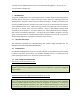
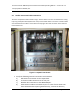
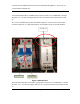
2.2 Confirm Front Panel Cable Connections
The slave unit (bottom module shown in Fig 1 and the master units are connected to the timing
tray using a backplane board (behind the units) and 4 coaxial cables in the front as shown. Make
sure that GPS antenna cable is connected to the top right hand side connector and TX antenna
to the bottom one.
Figure 1 Leopard Front Panels
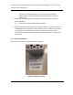
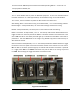
1. Verify the following external connections to the beacon:
a) GPS antenna connection to the Leopard Box
b) Tx antenna cable connection to the ‘TX’ port.
c) Weather box connection to the WEATHER port.
d) EvDO antenna cables to the EvDO Tx port. In cases of sites which have
been documented as requiring EvDO diversity, connect the diversity