
User's Manual

Document Name: MBS Leopard Transmitter Usert NOC Operating Manual
Version No: 1.5
Company Name: NextNav, LLC.
Confidential Page 12 9/17/2014
Page 12 of 13
2.6 Tune-up procedure not to exceed maximum TX power
A CSV file (configuration file) per transmitter are created by the NOC engineer based on the
installation parameters such as line lengths, antenna type etc. The TX output power level
setting is contained in the CSV file.
The output power is adjusted by the ‘PA gain” setting. This value in the CSV file is calculated by
a formula to set the output power (not to exceed 30W ERP). The variables used in the
calculation include PA Gain (Gpa), TX Antenna Gain (Gant), TX filter insertion loss (ILflt), internal
cable loss (ILint), external cable loss (ILext), and transceiver output power (PTCVR).
ERP (W) = 10^((PTCVR - ILint + Gpa - ILflt - ILext + Gant) / 10) / 1000
The PA gain setting should be set to a proper value so that total sum of net antenna gain and
cable loss coupled with PA output does not exceed 30 Watts EIRP, PEP (Peak Envelope Power) .
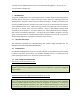
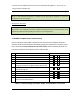
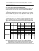
Table 2 is a list of all possible antennas and RF cable combinations with corresponding RF power
settings required to comply with the FCC requirement of 30 Watts EIRP Peal Envelope Power
(PEP).
Tx Band
PA Gain
(dB)
PA out
(dBm)
Antenna
Type
Antenna
Gain
(dBd)
Cable
Loss (dB)
ERP
(dBm)
ERP (W)
(PEP)
5 MHz
61.0 max
+43.18
DB586-Y
6.0
4.5 min
+44.78
29.4
SC433-
HF6LDF
2.5
1.0 min
+44.78
29.4
BCD-8707
6.5
5.0 min
+44.78
29.4
OD9-5
2.9
1.4 min
+44.78
29.4
2 MHz
60.3 max
+41.53
DB586-Y
6.0
2.8 min
+44.73
29.7
61.0 max
+42.23
SC433-
HF6LDF
2.5
0.0 min
+44.73
29.7
60.3 max
+41.53
BCD-8707
6.5
3.3 min
+44.73
29.7
60.6 max
+41.83
OD9-5
2.9
0.0 min
+44.73
29.7
IDB Modes with
interleaved 2
MHz and 5 MHz
channel
59.0 max
+41.33
DB586-Y
6.0
2.8 min
+44.53
28.4
SC433-
HF6LDF
2.5
0.0 min
+43.83
24.2
BCD-8707
6.5
3.3 min
+44.53
27.9
OD9-5
2.9
0.0 min
+44.23
26.5
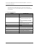
Table 2 Maximum allowable RF power settings with various antenna/cable
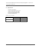
Note 1: PA module provides means of RF Gain control in steps of 0.1 dB from 0 to 65 dB.
Maximum PA Gain values listed in the table2 are required to ensure that conducted and
radiated spurious emission standards of Part 90 are met. The difference of PA output