
User's Manual

Document Name: WAPS Beacon NOC User Manual
Document No: JGR-NN-OP-102.00-Rev1.2
Version No: 1.2
Company Name: NextNav, LLC. Page 7 15-Nov-12
Page 7 of 7
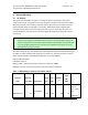
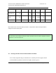
The TX output power level setting is contained in the CSV file.
The output power is adjusted by the ‘attenuation’ setting This value in the CSV file is
calculated by a formula to set the output power (not to exceed 30W EIRP). The
variables used in the calculation include PA Gain (G
pa
), TX Antenna Gain (G
ant
), TX
filter insertion loss (IL
flt
), internal cable loss (IL
int
), external cable loss (IL
ext
), and
transceiver output power (P
TCVR
).
EIRP (W) = 10^((P
TCVR
- IL
int
+ G
pa
- IL
flt
- IL
ext
+ G
ant
) / 10) / 1000
4.3 GPS Receive Antenna
GPS antenna should be installed such that it has clear view of sky. Ideally, you would keep the
antenna close to the ground away from obstruction
• Keep any horizontal blockage smaller than 10 degrees
• Obstruction Clearance guideline
– If it is 1 ft wide it should be at least 6 ft away
– If it is 10 ft wide, it should be at least 60 ft. away.
– If it is significantly less than 1 ft wide (like a guy wire, or a post) it should not
cause any measurable effect.
4.4 Product information
Modifications made to the product, unless expressly approved by NextNav, LLC could
void the user’s authority to operate the equipment.
NOTE: This equipment has been tested and found to comply with the limits for a Class A
digital device , pursuant to Part 15 of the FCC Rules. These limits are designed to
provide reasonable protection against harmful interference when the equipment is
operated in a commercial environment. This equipment generates, uses, and can
radiate radio frequency energy and, if not installed and used in accordance with the
instruction manual, may cause harmful interference to radio communications.
Operation of this equipment in a residential area is likely to cause harmful interference
in which case the user will be required to correct the interference at his own expense.