Precision Motion Control User Manual RPG Rotary Drive System FORM NO.
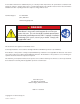
In accordance with Nexen’s established policy of constant product improvement, the specifications contained in this manual are subject to change without notice. Technical data listed in this manual are based on the latest information available at the time of printing and are also subject to change without notice. Technical Support: 800-843-7445 (651) 484-5900 www.nexengroup.com DANGER Read this manual carefully before installation and operation.
Table of Contents General Safety Precautions - -------------------------------------------------------------------------------------------------- 4 System Design Overview ------------------------------------------------------------------------------------------------------- 5 General System Requirements ------------------------------------------------------------------------------------------ 5 Ring Gear and Arc Segment Requirements------------------------------------------------------------------------- 6
GENERAL SAFETY PRECAUTIONS WARNING DANGER Use appropriate guarding for rotating components. Failure to guard could result in serious bodily injury. This product has moving parts that can crush or cut appendages. Provide adequate spacing or guarding from any operating product. WARNING WARNING Failure to properly support the load before disengaging the RPG system could cause serious harm to operators or equipment. Ensure proper guarding of the product is used.
SYSTEM DESIGN OVERVIEW General System Requirements • Unlike traditional gear systems, the Roller Pinion Gear (RPG) rotary drive system has zero mechanical clearance and requires a system preload for proper operation. This preload must remain relatively constant around the entire gear to obtain optimal system performance and life. To achieve this it is crucial that the bearing support system be as concentric as possible to the ring gear pitch circle diameter and not converge or diverge at any point.
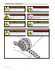
SYSTEM DESIGN OVERVIEW Ring Gear and Arc Segment Requirements • RPG solid ring gears are available in diameters up to approximately 750 mm [29.5 in.], beyond this the ring gears will consist of segments that will be joined together to form a complete ring. Arcs of various radiuses and lengths can also be provided. Throughout this document “ring gear” will be used primarily but will also apply to arc segments unless otherwise noted.
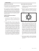
PROPER SYSTEM ALIGNMENT Pinion Shaft This distance must remain concentric within 0.02 mm [ 0.0008 in] The RPG system is available as solid round gears, segmented gears, or arc segments with internal or external teeth. The instructions that follow will use the reference “ring gears” but applies universally to all cases. Unlike traditional gear systems, the RPG System operates with no mechanical clearance and requires a preload.
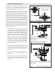
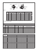
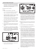
Through Hole Mounting of Alignment Tool Tapped Hole Mounting of Alignment Tool Alignment Tool Gear Segment Alignment Tool Gear Segment D E Gear Mounting Bolt A Through Hole B Alignment Tool Mounting Bolt E Gear Mounting Bolt C Tapped Hole Alignment Tool Mounting Bolt Figure 4 RPG Size Through Hole Mounting Tapped Hole Mounting Gear Mounting Hole E A B C&D D Through Hole Bolt 16 9 M8 x 1.25 M6 x 1.00 M6-50 M6-50 M8 20 11 M10 x 1.50 M8 x 1.
INSTALLATION RING GEAR INSTALLATION SOLID RING GEAR INSTALLATION In the following section “ring gear” will be used to describe solid ring gears, segmented ring gears, arcs, with internal or external teeth unless otherwise specified. 1. Carefully place the solid ring gear onto its mounting step, align the bolt holes, and insert the mounting bolts and hand tighten them.
ROLLER PINION INSTALLATION Note: There are two pinion mounting styles, shaft or flange mount. Refer to the following section that applies to your situation. In either case it is critical to minimize radial variance. It will effect pinion preload and positional accuracy throughout the run. Tightening Order 1 4 Bushing bolts Inner Bushing Half Outer Bushing Half 3 Shaft Mounted Pinion Installation 5 NOTES: • Refer to product drawings for shaft details.
10. Once the fasteners are fully torqued verify the pinion is centered on the gear. If not, measure the positional error and then remove the pinion as described in the Disengaging The Roller Pinion section on page 16. Repeat the pinion installation procedure and offset the pinion by the recorded error plus the previous off set value. When the pinion is fully torqued and properly centered then verify pinion concentric variation at the center of the pinion rollers as shown in Figure 15.
13. Clean the pinion flange and pilot where it will contact the adapter (if used) or gearhead flange inspecting for contaminates, burs, or surface defects that would interfere with full contact between the pinion and adapter (if used) or gearhead flange. 14. Apply a serviceable thread locking compound to the pinion mounting screws and assemble the pinion to the adapter (if used) or gearhead, leaving the mounting screws snug but do not tighten at this time. Figure 15 15.
17. Re-torque the mounting screws once more to the fullspecified torque value in Table 4 to ensure full torque has been reached on all fasteners. Tighten in the same order as above. 18. Repeat variance inspection Step 15 and verify the variance listed is achieved after fully torquing the pinion. If variance is out of specifications the pinion should be removed inspecting for contaminates, burs, or surface defects that would interfere with full contact between the adapter (if used) and gearhead flange.
3. Verify that the pinion rotational axis is as parallel as possible to the gears rotational axis, and the gear is centered between the pinion bearing flanges as shown in Figure 1. 7. 4. Rotate the preload adjustment screw clockwise to separate the pinion from the gear. This will ensure that clearance is initially present. Then seat the pinion into contact by turning the preload adjustment screw counterclockwise until a slight resistance is felt and then back the screw off 1/8 of a turn.
DISENGAGING THE ROLLER PINION 1. De-couple the load from the RPG system. 4. Progressively loosen non-adjacent bushing fasteners in the same order they were tightened until all are removed from the bushing (Refer to Figure 11). WARNING Failure to properly support the load before disengaging the RPG system could cause serious harm to operators or equipment. 5.
LUBRICATION The pinion needle bearings are sealed and lubricated for life and cannot be serviced. THK AFA grease is recommended for gear tooth lubrication. Nexen offers this grease under product number 853901. Greases for special applications such as food grade, vacuum, or others are allowed if they use a synthetic base, a polyurea thickener, and meet the following Kinematic Viscosity Levels: CST@40C = 25; CST@100C = 5. Contact Nexen for recommendations on alternative greases.
WARRANTY Warranties Nexen warrants that the Products will be free from any defects in material or workmanship for a period of 12 months from the date of shipment. NEXEN MAKES NO OTHER WARRANTY, EXPRESS OR IMPLIED, AND ALL IMPLIED WARRANTIES, INCLUDING WITHOUT LIMITATION, IMPLIED WARRANTIES OF MERCHANTABILITY AND FITNESS FOR A PARTICULAR PURPOSE ARE HEREBY DISCLAIMED.