USER's GUIDE MANUAL (Radar Object Detection Sensor)
Table of Contents I Table of Contents ........................................................ 1 II Contents ..................................................................... 2 III 3 IV Object Detection Capability ........................................ 3 V ............... 4 VI Radar Sensor .............................................................. 5~6 VII Display units ............................................................... 7~8 9~11 VIII IX Dimension .......................
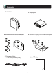
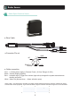
II Contents ● RADAR Sensor ● Display unit ● Wall Mount Included screw pack ● Bracket for Display unit Included screw pack ● Extension Cable → 9M (29ft) or 20M (65ft) 2
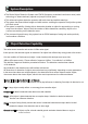
III System Description ● The Radar Object Detection System uses FMCW (frequency modulated continuous wave) radar technology to detect stationary objects and people in blind spots. ● This advanced system alerts the operator with both visual and audible warnings. ● The system has three distinct length and width modes, enabling the operator to adjust the system to fit their needs.
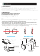
V Installation ◈ Sensor Mounting The installation site should be flat. Ideally the radar sensor should be mounted on the rear of the vehicles as close to the center as possible at roughly 1 meter above the ground. The sensor should be mounted in the upright position with cable exit on the sensor pointing downwards. ◈ Mounting angle Select the appropriate location to mount the sensor. a. Height tolerance (from ground); 1m +/- 0.3 m) b. Vertical angle tolerance +5 (up), -2° (down) c.
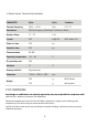
VI Radar Sensor Radar Object Detection Sensor ● Rear Cable ALARM TRIGGER B+ GND ● Connector Pin out GND 5 NC 3 RS485-B 2 4 1 VCC RS485-A ● Cable connection Red : + Vehicle power supply or Reverse Power ( 3A fuse: Range +9~24V) Black : Ground (Supply negative) Blue : Activation input (Trigger from vehicle, High active) changes the system status between standby and active.
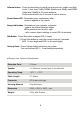
● Radar Sensor Technical Specification PARAMETER Value Units Condition Transmit frequency 24.06 ~ 24.
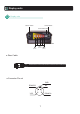
VII Display units Display units Dimmer button Volume button Power status LED Range indication Mode 3 (LED #3) (LED #5) Mode 1 (LED #1) ● Rear Cable ● Connector Pin out GND 5 RS485-B 2 1 NC 3 4 VCC RS485-A 7
Volume button : Press volume button to adjust volume level low, middle, and high Led # 1 (Low level 78dB), LED#2 (Middle level 85dB), and LED#3 (High level 104dB) at 0.3 meter distance. Press volume button for 3 seconds to switch silence. Power Status LED : Illuminates green continuously after power is applied to the system Range Indications : Illuminates to give operator a distance zone to the closest detected object.
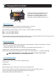
VIII Changing Detection Mode Dimmer button Volume button Power status LED ◆ ◆ ◆ ◆ ◆ LED # 5 is flashing (Furthest Detection zone 5) LED # 5, & 4 are flashing (Detection zone 4) LED # 5,4,& 3 are flashing (Detection zone 3) LED # 5 ~ 2 are flashing (Detection zone 2) All LEDs are flashing (Closest Detection zone 1) Range indication (LED #5) Mode 3 (LED #3) Mode 1 (LED #1) Mode Adjustment. 1) Press both “Dim” and “Vol” to enter hidden menu simultaneously for 3 seconds.
Mode 1 Mode 1.: 3.0 X 5.0 meter (Detection zone 5) Test Conditions Radar sensor (Height 1.0 meter) Test Person : 1.8 meter tall Radar sensor ZONE 1 1M ZONE 2 2M ZONE 3 3M ZONE 4 4M ZONE 5 5M 6M 7M 8M 9M 10M 1 A ea → 1㎡ Mode 2 Mode 2.: 4.0 X 6.0 meter (Detection zone 5) Radar sensor Test Conditions Radar sensor (Height 1.0 meter) Test Person : 1.8meter tall.
Mode 3 Mode 3.: 6.5 X 9.0 meter (Detection zone 5) Test Conditions Radar sensor (Height 1.0 meter) Test Person : 1.8meter tall.
Dimension ● Radar Sensor (mm) 110 106 108 34 ● Display units (mm) 65 20 54 15 IX 67.
● Radar Bracket (mm) ● Display Bracket (mm) 13
WARNING RISK OF ELECTRIC SHOCK DO NOT OPEN To reduce the risk of electric shock do not remove cover(or back) No user serviceable parts inside. Refer servicing to qualified service personnel. The lightning flash with arrowhead symbol,within an equilateral triangle,is intended to alert the user to the presence of uninsulated "dangerous voltage" within the product's enclosure that may be of sufficient magnitude to constitute a risk of electric shock to persons.