Operation Manual LRB 6000CI LASER RANGE FINDER BINOCULARS 105 Sparks Ave.
ii
IMPORTANT INFORMATION Read prior to activation You have just purchased a sophisticated electro-optical device that emits invisible laser radiation. To operate it properly, please read this manual carefully. NEVER direct laser beam at the eyes of people or animals NEVER aim the unit at the Sun or bright sources of light NEVER subject the unit to impacts NEVER transport the unit without its case NEVER disassemble the unit.
Caution - use of optical instruments such as binoculars, loupes, mirrors, lenses, etc. with this product increases eye hazard Note: Avoid eye exposure to direct laser beam or its close reflection Prevent bright light from focusing through the eyepieces Never aim the unit at highly reflective objects like mirrors and retroreflective surfaces, which are in close proximity to the laser rangefinder. This can lead to the permanent damage of the photoreceiver incorporated into the device.
TABLE OF CONTENTS 1. BRIEF DESCRIPTION.................................................. 2 2. DEVICE APPEARANCE .............................................. 4 3. DELIVERY SET............................................................ 7 4. SPECIFICATIONS ........................................................ 8 5. OPERATION INSTRUCTIONS.................................. 10 Installing the battery..................................................... 10 Using the Device ............................
CAREFULLY READ ALL THE INSTRUCTIONS PRIOR TO USE! FAILURE TO OBEY THE INSTRUCTIONS WILL VOID THE WARRANTY AND MAY CAUSE INJURY! 1. BRIEF DESCRIPTION LRB 6000CI Laser Rangefinder Binoculars (System) is an advanced laser range finder system that enables instant distance, speed, vertical and horizontal angular measurements. An outstanding optics provides a sharp, clear image under any observation conditions. The unit utilises time-of-flight method of distance and speed measurement.
Key Features of the LRB 6000CI Laser Rangefinder Binoculars Modern digital circuitry allows targeting through most types of glass First, last or the most reflective target acquisition Meters/Yards/Mils/Degrees/KMH/MPH display Last 10 measurements recall Selectable reticle shape (+ or ) Gating capability Speed detector Accurate digital compass Accurate digital inclinometer RS-232 bidirectional communication GPS interoperability (PLGR/DAGR protocol) Auto shutoff time – 16 seconds
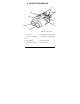
2. DEVICE APPEARANCE 4 6 1 7 5 8 3 2 Fig. 1.
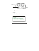
1 9 10 11 Fig.
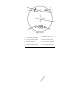
6 1 8 7 2 4 3 Fig.
3. DELIVERY SET Standard delivery set for LRB 6000CI includes: Qty LRB 6000CI Carrying case Neck strap User’s manual Warranty card Cleaning cloth Computer cable CD with communication software Hard case 9V non-magnetic Lithium battery 1 pc. 1 pc. 1 pc. 1 pc. 1 pc. 1 pc. 1 pc. 1 pc. 1 pc. 1 pc. Optional items GPS cable Exact delivery set depends on details of a contract or purchase order.
4. SPECIFICATIONS Optics Magnification Objective lens diameter Exit pupil diameter Field of view Type of coating Interpupillary distance Dioptre adjustment range 7x 50 mm 7.
Compass Measured azimuth range Accuracy 6400 mils /360 ±1 Inclinometer Measured elevation range ±60 Accuracy ±1 Yes (Meters or Yards) Height measuring Power Battery Battery capacity 9V Lithium (non-magnetic) Min 5,000 measurements (Scanning regime) 'Low Battery' indicator Yes Environmental Operational temperature range Storage temperature range Mechanics Tripod thread Weight without battery Weight with hard case Dimensions -25…+50oC (-13…+122oF) -45…+65oC (-49…+149oF) ¼” x 20 TPI 1.3 kg 3.
5. OPERATION INSTRUCTIONS Installing the battery Open the battery compartment using a suitable tool, or a coin. Insert a 9V Lithium non-magnetic battery provided with your device Connect the battery to the battery snap Refit the battery compartment and tighten the screw. If the battery compartment cover does not close tightly and evenly, check that the battery snap wires are neatly packed inside the battery compartment and the cover is aligned over the edge of the battery compartment.
Using the Device The LRB 6000CI operational procedures are design to allow the user to use most applicable options in the fastest time possible. To activate it, press and hold Action button (6, Fig.1) for one second. At start the unit comes into Ready to Measure mode indicated by the word ‘READY’ on the display visible through the eyepiece. Pressing Action button (6, Fig. 1) again will initiate measurement procedure.
Factors affecting measuring distance Though maximum measurement distance depends on target reflectivity, weather conditions and other conditions, for most targets the unit will provide accurate ranging for up to 4,000 meters. Under good conditions a large size target can be measured up to 6,500 meters. Target reflectivity depends on its color, surface finish, size, shape, position in relation to the laser beam, etc. Bright target colors are more reflective than darks.
Target selection logic On its way towards the target the laser beam may be reflected from various objects, thus decreasing ranging accuracy. The smaller, the farther, and the less reflective is the target – the higher is the possibility of obtaining an incorrect measurement. To improve accuracy the unit has a built-in target selection logic that allows user the option of choosing which target to range: the nearest (‘first’), the farthest (‘last’), or the most reflective (‘auto’).
Scanning regime the unit repeatedly measures and displays results every second while A button is pressed. To activate Scanning regime press and hold Action button in Ready mode. The unit will work in Scanning regime while Action button is pressed. Scanning or Individual Measurement regimes are available for any selected mode of measurement.
o Std – allows the user to select single action measurements: o Distance only (d) Compass Only (C) o Elevation Only (E) o Speed Only (S) o Height Only (H) o Speed + Distance (Sd) o Distance +Compass + Elevation (dCE) Unit – allows the user to select units of desired measurements, o Distance from M to Y o Compass & Elevation from Mils to Degrees o Speed from KMH to MPH* * this option is only available if Std Speed is selected rEc – allows data recall of the last 10 measurement results, o CLr – C
AUtO – Last Target Measurement* PLGr – Communication to PLGR GPS* o PC – Communication to PC* o Reticule – Change reticule from + (cross) to (rectangle) o CAL – Compass calibration ▪ CALc – compass calibration (CI model only) ▪ Corr – accuracy correction of active parameters *not shown in the menu if currently selected o o Accuracy correction If the System produces any measurement errors that lie beyond unit specification, it may be an indication that unit requires calibration similar to one conducted at
Active mode of measurement (Std) Correction parameter S, Sd, d Distance Condition Install unit at 1 meter1 from flat target2 C, E Put unit in a level plane Azimuth and and aim it to the North elevation direction3 dCE Install unit at 1 meter1 Distance, from flat target2 azimuth and controlling its level elevation position and direction to the North 1 – Accuracy of correction will depend on accuracy of installation against target. If distance is 0.9 meters, then unit will have 0.
Compass calibration If the System was exposed to a strong magnetic field or was not in use for a long time, the compass accuracy may diminish. To return the compass into working condition: Select CALc from CAL menu Keeping the unit horizontally, perform one full rotation around vertical axis within half a minute and then one full rotation around vertical axis with device upside down during half a minute. If one rotation does not restore calibration – perform two rotations.
Gating mode In this mode gating function is activated: here user can set the minimal distance to the target, any object closer than the gating distance will be ignored. To select Gating Mode: Select GAtE from main menu Minimal gating distance of 0 meters (display: 000 m) will be initially set, further pressing M button will increase gating distance by 100 m up to 3,900 m. When the desired distance is reached – select it by pressing Action button.
Data Recall mode In Data Recall mode results of the last 10 measurements can be displayed. Measurement results are saved in on-board memory in sets depending on the parameters set for measuring, for instance, if only distance is measured - the set will consist of one number, if distance and azimuth are measured – the set will consist of two numbers. To enter Data Recall mode select rEc from the main menu. First measurement set number (display name: rEc 1) will start flashing.
Computer interconnectivity The unit supports RS-232 interface. Physical connection is performed through connector with threaded coupling mechanism, designed for the heavy-duty outdoor applications. Note: Do not apply excessive force when disconnecting cable. Damage to cable or connector resulting from improper treatment is not covered by warranty. To attach the cable to the rangefinder match the key on the plug (1, Fig.
GPS interconnectivity LRB 6000CI can transmit the acquired data to a GPS receiver using DB15 connector and PLGR/DAGR protocol. An optional cable is required. To work with GPS, perform the following steps: Switch the rangefinder to PLGr mode; Choose dFLt measuring mode; Connect the rangefinder and GPS unit with the cable. For each measurement GPS will display the absolute coordinates of your target. Note: If the rangefinder is not set initially to dFLt mode, the GPS will not operate properly.
6. BEST MEASURING TECHNIQUE Laser range finder measures distance by catching laser beam reflected from the target. Everything that improves reflection increases the measurement reliability and maximum range. 1. Use tripod when ranging remote targets. The longer is the distance, the greater is the beam shift due to hand tremor. 2. Aim at a surface on the target that is the closest to perpendicular to the laser beam. The closer you get – the stronger will be the reflection. 3.
reflections from all objects closer than the gating distance will be ignored. This is especially effective when ranging in unfavourable atmospheric conditions, that is, in the rain, fog, haze or in the bright sun. Gating provides better results than the “last” target selection, but it requires preliminary rough distance estimation to cut off all objects closer than the chosen one. Note: Gating setting is remembered by the System until altered.
7. STORAGE AND MAINTENANCE The unit is a sophisticated precision optical instrument equipped with laser and electronics. Therefore, it should be handled with due care. Keep away from direct sunlight. Avoid impacts, jolts, dust, moisture, and sharp changes of temperature. Do not use the device at temperatures higher than 50oC (122oF). Do not touch optical surfaces. Doing so may damage the anti-reflection coating. Clean optical surfaces only with professional camera lens cleaning supplies.
8. TROUBLESHOOTING Ranging does not work. The display is transparent. Check the charge of the battery. Replace it if it is weak. Ranging does not work. The display indicates results of the last measurement. Wait for 8 seconds until the display becomes transparent, and press the Action button again. Black dots are visible on LCD. Liquid Crystal Display may have small black dots, scratches and other blemishes inherited from the manufacturing process.
9. WARRANTY NEWCON warrants this product against defects in material and workmanship for one year from the date of the original purchase. Longer warranty is available, subject to the terms of the specific sales contract. Should your Newcon product prove to be defective during this period, please deliver the product securely packaged in its original container or an equivalent, along with the proof of the original purchase date to your Newcon Dealer.
10. CUSTOMER SUPPORT Should you experience any difficulties with your NEWCON OPTIK product, consult the enclosed manual. If the problem remains unresolved, contact our customer support department at (416) 663-6963 or toll free at 1877-368-6666. Our operating hours are 9am-5pm, Monday - Friday, Eastern Standard Time. At no time should equipment be sent back to Newcon without following the instructions of our technical support department. NEWCON OPTIK accepts no responsibility for unauthorized returns.
11. QUALITY CERTIFICATE Serial number _____________________________ The unit indicated above has passed the quality inspection.
R1 – 2.