Operation Manual NEWCON OPTIK ™ 2007 Printed in Canada LONG RANGE LASER RANGE FINDER LRB 20000 In USA: 2331 Superior Ave. Cleveland, OH 44114 In Canada: 105 Sparks Ave.
NOTES: 19. ACCEPTANCE CERTIFICATE LASER RANGEFINDER LRB20000 Serial Number___________corresponds to all technical specifications and has passed the quality inspection.
18. CUSTOMER SUPPORT Should you experience any difficulties with your Newcon OPTIK product, consult the enclosed manual. If the problem remains unresolved, contact our customer support department at 1(416) 663-6963 or Toll free at 1-877-368-6666. Our operating hours are 9am-5pm, Monday - Friday, Standard East Time. IMPORTANT INFORMATION Read prior to activation You have just purchased a complicated electronic device, which emits hazardous invisible laser radiation.
17. WARRANTY Features of the LRB 20 000 Laser Range Finder Binocular • • • • • • Digital data output First or last target indication Built-in compass Lightweight Rugged Meet all military specifications NEWCON OPTIK warrants this product against defects in material and workmanship for one year from the date of the original date of consumer's purchase, but no more than 18 months from the date of manufacturing. Longer warranty periods are available, subject to the terms of specific sales contract.
If you use Windows 95, 98 or ME: - Turn computer on and enter the BIOS SETUP in accordance with the computer documentation. - Set the address of LPT port as 378h, and port type as EPP. Register the new settings. - After OS on your computer has been loaded, insert the supplied diskette into the floppy disk drive. - Run program with the name “BDEPP5.EXE”. - Perform measurements as described in the manual. The results will be shown in the communicator program window. To exit the program, press the space key.
1. OVERVIEW RANGEFINDER BINOCULAR LRB 20000 is an advanced Laser Rangefinder system that provides instant distance measurements consistently and accurately. The stereoscopic device provides convenient observation with both eyes. Therefore, the LRB 20000 eliminates a need for two separate devices (binocular and rangefinder) combining both requirements in a single device. It is designated for industrialtechnical purposes, ground surveillance, observation of individual targets and measurement.
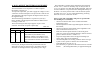
16. DATA OUTPUT TO EXTERNAL EQUIPMENT The measured data can be exported to a remote computer through the connector X2. To export the output data, you must to apply the voltage of 3 to 8 V from the connected computer to the pin 9 of the connector X2. The amplitude of the output signals will depend on the value of the supplied voltage. The measured range information is exported in cycles by a binary decimal code through four data and three address buses according to Table 16.1.
To secure trouble-free operation of the rangefinder: - be prompt in replacing the rechargeable battery by freshly charged when the red LED in the left-hand eyepiece of the range finder starts to illuminate; - keep the range finder dry at all times especially in the cold season of the year; - after exposure to subzero temperatures keep the range finder at room temperature for at least two hours before unpacking and then mop up the condensed moisture; - while operating the range finder at temperatures above 3
15. RECHARGEABLE BATTERY HANDLING 2. ABBREVIATIONS 15.1. The rechargeable battery is supplied in discharged condition. 15.2. While handling the battery, be certain to: - avoid contact with any bare circuit components while charging the battery; - strictly comply with the prescribed charging/discharging procedures. NEVER: - dismantle the battery; - store the battery together with acids, or batteries using acids. 15.3. The battery is subject to charging at an ambient temperature of (20±5) °C.
3.
.3.5. The individual SPTA set is packed in the case 4 (Fig. 7). The case contains the spare rechargeable battery, pencil, eraser, cloth and coordinate converter. The principal parameters of the emitter with serial number _______, fitted into the rangefinder, are as follows: Ambient temperature 12.
- 4. SUPPLIED ACCESSORIES Description Rangefinder Tripod (optional) Angular mount (optional) Rechargeable battery Fuse link VP1-1 1,0 A 250 V Sealing ring Framed lens Membrane Eye shield Diaphragm Pencil TM, M, CT, T Wrench Synthesized fiber brush KXOOK No. 7 Coordinate converter Cable Cable Cable Cable Cable Designation AEP 41.46.712 G 42.14.067 G 42.21.812 10D-0,55С-1 G 68.79.19302 G 44.21.885 AEP 75.48.092 G 47.92.131 AEP 73.54.031 Qty 1 1 1 Remarks - 2 - 5 - 2 1 2 2 1 1 1 - AEP 87.61.
11.3. To correct problems by using the individual SPTA set proceed as follows (see Fig. 6). 11.3.1. To replace the fuse link 2 in the protection device: - Unscrew the threaded cover from the housing of the protection device; - Remove the defective fuse link; - Insert the spare fuse link from the SPTA set; - Screw the cover on the housing of the protection device. 11.3.2.
5. PRINCIPLES OF WORK 5.1. The LRB 20000 assembly (Fig.1) consists of rangefinder 1 mounted on the angular mount 2. The latter is mounted on the tripod 3. 5.2. Rangefinder (Fig.2) is designed for terrain observation and measuring the distance to the closest or next-in range target caught in the beam. It works with the principle of measuring the light pulse round-trip time.
- remove the moist silica gel from the case and fill the case with the fresh one. Moist silica gel may be subjected to multiple dehydrations at (120±3) °C without any deterioration of its properties. Using a microwave oven is allowed. To dehydrate the silica gel, proceed as follows: - place the silica gel in a clean metal vessel; - place the vessel on the heat source providing heating up to (120±3) °C. Measure the temperature directly on the silica gel; - see the silica gel changing its colour.
5.3. Angular Mount (Fig. 4) is intended for mounting rangefinder on a tripod, aim the rangefinder to the target and measure the azimuth and elevation values. The main part of the Angular Mount (AI) is body 15, which incorporates the elevation and azimuth worm-gear drives. Use adjustment knobs 1 and 7 for the fine tuning of the rangefinder. To perform initial tune-up, turn the unit through the desired angle. Read the angles read on azimuth circle 14 and scale 5.
10.5. In-service Maintenance. 10.5.1. During in-service maintenance, the range finger is checked for serviceable condition in accordance with Steps 1 through 10 of Table 9.1. 10.5.2.The unit is not to be dismantled during in-service maintenance. 10.5.3. For the servicing scope, refer to Table 10.3. The length of each leg is adjusted by retracting or extending the moving section. The coupling nut 4 must be loosened first to change the leg length.
Table 10.2 6.2. According IEC 825 standard the rangefinder belongs to the third class device of laser radiation hazard.
Table 10.1 Operations 1. Cleaning external optical surfaces (when required) 2.Charging of rechargeable battery (when required) Procedure as per Article. 10.6.2 Materials, tools and accessories Lens Brush No. 7 (made of synthetic fibre) Absorbent optical cotton Alcohol Section 15 10.4. Daily Servicing. 10.4.1. During the Daily Servicing, the rangefinder is checked for serviceable condition in accordance with Steps 1 through 10 of Table 9.1. 10.4.2. For the daily servicing scope, see Table 10.2. 6.4.
7. PREPARING FOR USE 7.1. Choose an observation post. 7.2. Rotate the objective frame to bring the reticle to sharp focus. 7.3. Check the battery voltage and the rangefinder before operation. 7.3.1. To analyze the battery voltage, set the ON-OFF selector switch to the ON position and check if the Low Battery indicator glows red in the left-hand eyepiece. If it does, replace the battery. SET SELECTOR TO OFF BEFORE REPLACING THE BATTERY! 7.3.2.
Table 9.1, continued Items to check, test procedure Sensitivity, indexing uniformity and balance of the magnetic needle. Proceed as directed under 7.6.2. AI azimuth and elevation adjustment knobs must not be loose. Technical requirement Send the unit for repair if even a single requirement of 8.6.2. is not satisfied. If necessary, tighten bushings on knob end facets. 10. MAINTENANCE 10.1. Maintenance Organization and Procedure. General Instructions. 10.1.1.
- Rotate the azimuth dial to align the base reference value with the zero wheel. Now the rangefinder is aligned with the base line within 30.00 mils; Turn the clamping handle to lock the azimuth dial in the determined position. 7.5.2.
Plot the target on the map using the obtained rectangular coordinates. 8.9. When using the rangefinder under the conditions of insufficient light, set the ILLUM. selector switch to ON. 8.10. If a target is located against an intense background (bright sky, sunlit snow or sand, etc.), the range display may indicate as if more than one target is caught in the beam, and the range indications may differ every time that MEASURE L button is depressed.
The A1 and A2 values are entered with their respective signs. If the ER "0" value is other than zero, the respective correction is to be taken into account while operating the range finder. The error value is subtracted from the elevation measurement, if the latter is positive, and added, if it is negative. 7.6.2. To check compass, set up the AI for operation. Then, check the sensitivity and balance the needle.
- Vertical angles up to 0.80 mils and elevation angles falling within ± 0.40 mils may be read off the reticle with a maximum accuracy of 0.05 mils. 8.7. To determine the polar coordinates, proceed as follows: - Use the compass to orient the Angular Mount as directed under 7.5.3; - Aim the rangefinder to the object; - Read the azimuth of the object; - Range the object as directed under 9.3. 8.8.
If there is more than one target on the laser beam path (a wire in front of a building), the decimal point is displayed in the least significant digit position of the range indicator. In this event, the rangefinder may be used to range the first or the last target by pressing the MEASURE 1 or MEASURE L button respectively. If it is possible, repeat the target ranging once or twice. If the obtained range is correct, the results will not differ by more than 5 m. 8.4.
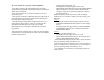
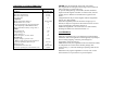
Individual SPTA set 1 - Rechargeable battery 10D-0,55С-1; 2 - Fuse link VP1-1 1,0А 250 V; 3 - Pencil; 4 - Sealing ring; 5 - Eye shield; 6 - Framed lens; 7 - Cloth; 8 - Eraser; 9 - Wrench; 10 - Coordinate converter; 11 - Charging device; 12 – Protection device; 13 Indicating silica gel; 14…18 - Cables; 19 - Membrane; 20, 21 Cover; 22 - Diaphragm; 23 - Brush No. 7 (made of synthetic fibre) Fig. 6 Add 60.00 mils to the first value if it is exceeded by the second.
Laser rangefinder binoculars LRB 20000 1 - Rangefinder; 2 - Angular Mount; 3 - Tripod Fig. 1 Tripod mount 1 - Mounting head; 2 - Base; 3 - Legs; 4 – Nut Fig.
Angular Mount 1 - Adjustment knob; 2 - Lever; 3 - Bracket; 4 - Retainer; 5 Scale; 6 - Framed lens; 7- Adjustment knob; 8 - Compass; 9 Nut M8; 10 - Framed lens; 11 - Knob; 12 - Support; 13 - Level UK-10; 14 – Azimuth circle; 15 – Body Rangefinder rear view 1 - Housing; 2 -MEASURE 1 and MEASURE L buttons; 3 Belt; 4 - Panel; 5 - ILLUMINATION toggle switch lever; 6 Binocular eyepiece; 7- Screw; 8 - Indicator eyepiece; 9 - Plug МР-1; 10 - Battery section cover; 11 - ON-OFF toggle switch lever Fig. 4 Fig.
Fig. 3.