
Install Instructions


12
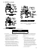
b. Align weld seams in pipes and use a slight
twisting motion to FULLY insert male end into
female end of joint. Ensure bead in male end
of pipe is below locking band and rest against
the end of the female pipe. Verify the factory-
installed gasket is not dislodged or cut.
c. Tighten locking band by HAND with a 5/16”
nut driver until snug plus ¼ turn. DO NOT
SECURE JOINTS WITH SHEET METAL
SCREWS OR POP RIVETS. DO NOT
PUNCTURE THE VENT SYSTEM!
d. Once the installation is complete, operate
appliance and inspect all joints to ensure that ue
gases and/or liquid condensate will not escape.
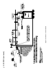
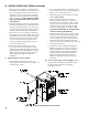
D. Separate Horizontal Venting System. See Figures 4A,
4B and 5. See Figure 28 for Blower Vent Connector
Assembly.
Vent Piping –
1. This boiler is supplied with components as standard
equipment for installation of the separate horizontal
venting system.
2. Do not exceed maximum vent lengths. Refer to
Table 4.
3. Recommended horizontal installation consists
of vent being sloped down ¼ inch per foot away
from boiler. See Figure 4A. See Figure 4B for an
alternate horizontal installation.
4. Use appropriate designed thimbles when passing
through combustible walls (thimble use optional for
noncombustible walls). Insert thimble through wall
from outside. Secure outside ange to wall with
nails or screws, and seal ID, OD and vent holes with
sealant material. Install inside ange to inside wall,
secure with nails or screws, and seal with sealant
material.
5. For noncombustible wall application when thimble
is not used, size opening such that bell with locking
band attached cannot pass through.
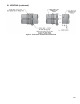
6. Join vent terminal to vent pipe. See Figure 5.
7. Insert vent pipe through thimble/opening from
outside and join to vent system. Apply sealant
between vent pipe and opening/thimble to provide
weathertight seal and prevent entry of combustion
products into building.
III. VENTING (continued)
10. Plan venting system to avoid possible contact with
plumbing or electrical wires. Start at vent connector
on top of boiler and work towards vent terminal.
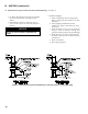
11. If a non-standard length pipe is required:
Gasketed Vent System: The use of the adjustable
length pipe (P/N 8116319U) is recommended to
complete a non-standard pipe length. This pipe
requires a minimum installed length of 12¾ inch
and can adjust across a 7 inch gap up to a maximum
of 19¾ inch long. (Note for the adjustable pipe
the installed length should be measured from the
centerline of the bead on the male end of the rst
pipe to the end of the female pipe excluding the
locking band of the second pipe with a single
gasket.) Only in the event the adjustable length pipe
is not sufcient a standard length pipe may be cut
using the procedure outlined below for the Gasket-
Less Vent System.
12. Vent connectors serving appliances vented by
natural draft shall not be connected into any portion
of mechanical draft systems operating under positive
pressure.
WARNING
Never exceed maximum installed length of 19¾
inches for adjustable length pipe.
Risk of ue gas leakage is possible.
NOTICE
Cut must be square with pipe and led or
sanded smooth before joining. Carefully ensure
roundness of cut pipe by hand with gloves before
installing. Seal joint with RTV specied in this
manual.
C. Install Vent Pipe, Gasketed Vent System.
1. Procedure for Joining New Yorker Gasketed Vent
Pipe and Fittings. See Figure 3.
a. Wipe the male end of each joint using an alcohol
pad to remove any dirt and grease.