
Install Instructions

52
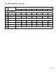
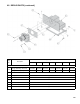
Table 16: Pilot Burner Location
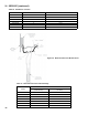
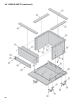
Figure 30: Differential Pressure Measurement
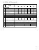
Table 17: Differential Pressure Switch Settings
Model Main Burner with Pilot Bracket Pilot Burner Located Between Main Burners *
PVCG30B 2 2 & 3
PVCG40B 3 3 & 4
PVCG50B 4 4 & 5
PVCG60B 5 5 & 6
PVCG70B 6 6 & 7
PVCG80B 7 7 & 8
PVCG90B 8 8 & 9
* Main burners numbered left to right as viewed from front of boiler.
Model
Minimum Differential Pressure
Sea Level to 4,999 Ft.
(Natural Gas)
Sea Level to 4,999 Ft.
(LP Gas)
PVCG30B 1.32” w.c. 1.32” w.c.
PVCG40B 1.17” w.c. 1.17” w.c.
PVCG50B 1.47” w.c. 1.17” w.c.
PVCG60B 1.25” w.c. .88” w.c.
PVCG70B 1.00” w.c. .80” w.c.
.PVCG80B 1.00” w.c. .88” w.c.
PVCG90B 1.00” w.c. .88” w.c.
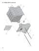
XI. SERVICE (continued)