
Install Instructions

49
A. General. Inspection and service should be conducted
annually. Turn off electrical power and gas supply while
conducting service or maintenance. Follow instructions
TO TURN OFF GAS TO APPLIANCE. See Figure 22.
CAUTION
Label all wires prior to disconnection when
servicing controls. Wiring errors can cause
improper and dangerous operation. Verify
proper operation after servicing.
B. Low water cutoff (if so equipped).
Probe Type (Annual Service). Probe type LWCO
should be removed once a year, examined and
cleaned of any dirt accumulations to assure proper
operations. Do not attempt to repair mechanisms in the
eld. Complete replacement mechanisms, including
necessary gaskets and installation instructions, are
available from the manufacturer.
C. Vent System. Inspect for obstructions, soot
accumulation, proper support, and deterioration of pipe,
ttings, and joints.
1. Clean terminal screens. Terminals must be free of
obstruction, undamaged, with screens securely in
place.
2. Terminal and wall thimbles (if used) must be
weathertight. Penetration through wall must prevent
entry of combustion products into building.
3. Pipe must be full round shape, and show no damage
from impact or excessive temperature.
4. Pipe must be supported at minimum ve (5) foot
(1.5 m) intervals and must not sag.
5. All vent joints must be secure and watertight.
6. All joints must be secure and airtight. Horizontal
vent tee drain or vertical vent tee drain (if used)
must have minimum 6 inch trap and allow
condensate to ow freely. To Clean:
a. Disconnect drain tube from drain tting.
b. Flush drain tube with water. Fill trap with water.
c. Securely fasten drain tube to drain tting,
providing gas-tight and watertight seal.
7. If pipe must be disassembled for removal of
obstructions or resealing of joint, see Section III,
Paragraph C.
D. Boiler Flue Passages. Inspect for blockage or soot
accumulation.
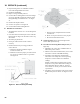
1. Remove Main Burners. See Figure 29.
a. Remove front door.
b. Disconnect pilot tubing and pilot lead wires at
the gas valve.
c. Remove wires to Flame Roll-out Switch.
d. Remove Burner Access Panel.
e. Mark location of Main Burner with Pilot Bracket
on gas manifold.
f. Hold Main Burner on throat. Lift front of
burners to clear orice. Burner which holds pilot
can be removed by lifting the burner adjacent to
its right rst.
2. Disconnect Vent Connector and Vent Pipe from
Blower Outlet.
3. Remove Jacket Top Panel.
4. Disconnect the Black and Gray Silicone Tubing
from the Canopy.
5. Disconnect Wiring Harness from Blower Motor.
6. Remove Canopy/Blower Assembly.
a. Loosen the (4) screws from Canopy.
7. Remove Flue Gas Bafes. Inspect Flue Gas Bafes
for deterioration.
8. Inspect ue passages. Clean with ue brush. See
Figure 29.
WARNING
This boiler must only be serviced and repaired by skilled and experienced service technicians.
If any controls are replaced, they must be replaced with identical models.
Read, understand and follow all the instructions and warnings contained in all the sections of this
manual.
Never jump out or bypass any safety or operating control or component of this boiler.
Read, understand and follow all the instructions and warnings contained in ALL of the component
instruction manuals.
Assure that all safety and operating controls and components are operating properly before placing
the boiler back in service.
Keep boiler area free and clear of combustible materials, gasoline and other ammable vapors and
liquids.
Do not place any obstructions in boiler room that hinder ow of combustion and ventilation air.
XI. SERVICE (continued)