
Install Instructions

25
V. GAS PIPING
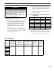
Table 5: Gas Ratings
For materials or conditions other than those listed
above, refer to National Fuel Gas Code, ANSI Z223.1
/NFPA54, or size system using standard engineering
methods acceptable to authority having jurisdiction.
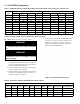
Table 6: Specic Gravity Correction Factors for
Natural Gas
WARNING
Failure to properly pipe gas supply to boiler may
result in improper operation and damage to the
boiler or structure. Always assure gas piping is
absolutely leak free and of the proper size and
type for the connected load.
An additional gas pressure regulator may be
needed. Consult gas supplier.
A. Size gas piping. Design system to provide adequate gas
supply to boiler. Consider these factors:
1. Allowable pressure drop from point of delivery to
boiler. Maximum allowable system pressure is ½
psig. Actual point of delivery pressure may be less;
contact gas supplier for additional information.
Minimum gas valve inlet pressure is stamped on
the rating label located in the boiler’s vestibule
compartment.
2. Maximum gas demand. Refer to the boiler’s input as
printed on its rating label. Also consider existing and
expected future gas utilization equipment (i.e. water
heater, cooking equipment).
3. Lengthofpipingandnumberofttings.Referto
Table 7 for maximum capacity of Schedule 40 pipe.
Table 8 lists equivalent pipe length for standard
ttings.
4. Correctionsforthespecicgravityofnaturalgas
can be found in Table 6.
Specic
Gravity
Correction
Factor
Specic
Gravity
Correction
Factor
--- --- 0.85 0.81
--- --- 0.90 0.82
0.60 1.00 1.00 0.78
0.65 0.96 1.10 0.74
0.70 0.93 1.20 0.71
0.75 0.90 1.30 0.68
0.80 0.87 1.40 0.66
Model
Natural/LP
Maximum
Gas Pressure
(in. w.c.)
Natural
Minimum Gas
Pressure
(in. w.c.)
Inlet to Gas Valve
LP Minimum Gas
Pressure
(in. w.c.)
Inlet to Gas Valve
Natural
Manifold
Pressure
(in. w.c.)
LP Manifold
Pressure
(in. w.c.)
PVCG30B
14 4.5 11.5 3.5 10.0
PVCG40B
PVCG50B
PVCG60B
PVCG70B
PVCG80B
PVCG90B