
Install Instructions


21
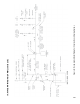
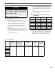
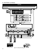
Figure 13: Recommended Piping for Combination
Heating & Cooling
(Refrigeration) System
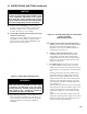
NOTICE
New Yorker recommends sizing the system
circulator to supply sufcient ow (GPM) to allow
a 20°F temperature differential in the system.
When sizing the system circulator, the pressure
drop of all radiators, baseboard and radiant tubing
and all connecting piping must be considered.
E. Install circulator with anges, gaskets and bolts
provided. Circulator harness allows circulator to be
mounted on supply or return. Connect harness to
circulator and secure any excess conduit.
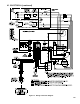
F. Install supply manifold, pressure/temperature gauge
and pressure relief valve.
See Figure 12. Pressure Relief Valve must be installed
with spindle in vertical position. Installation of the
relief valve must comply with the ASME Boiler and
Pressure Vessel Code, Section IV.
WARNING
Pressure relief valve discharge piping must be
piped such that the potential of severe burns
is eliminated. DO NOT pipe in any area where
freezing could occur. DO NOT install any shut-off
valves, plugs or caps. Consult Local Codes for
proper discharge piping arrangement.
G. Space heating and domestic water heating with Link
SL™ water heater. Install Link SL™ water heater as a
separate heating zone. Refer to Link SL™ Installation,
Operating and Service Instructions for additional
information.
Figure 12: Supply Water Manifold Piping
IV. WATER PIPING AND TRIM (continued)
H. If boiler is used in connection with refrigeration
systems, boiler must be installed with chilled medium
piped in parallel with the heating boiler using
appropriate valves to prevent chilled medium from
entering boiler. See Figure 13.
I. If boiler is connected to heating coils located in
air handling units where they may be exposed to
refrigerated air circulation, boiler piping must be
equipped with ow control valves or other automatic
means to prevent gravity circulation of boiler water
during the cooling cycle.
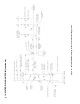
J. Use a boiler bypass if the boiler is to be operated
in a system which has a large volume or excessive
radiation where low boiler water temperatures may be
encountered (i.e. converted gravity circulation system,
etc.).
Install pipe tee between circulator and boiler return
along with second tee in supply piping as shown in
Figure 14 or 15. Bypass should be same size as the
supply and return lines with valves located in bypass
and supply outlet as illustrated in Figure 14 or 15 in
order to regulate water ow to maintain higher boiler
water temperatures.
After the boiler is operational (reference Section VIII.
System Start-Up) set by-pass and boiler supply valves
to half throttle position to start. Operate boiler until
system water temperature reaches normal operating
range.
Adjust valves to provide 180° to 200°F supply water
temperature. Opening the boiler supply valve will raise
system temperature, while opening the by-pass valve
will lower system supply temperature.