
Install Instructions

10
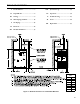
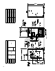
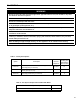
Table 3: Vent System Components
Vent System Component
Part
Number
Equivalent
Feet of Pipe
3” Dia. Pipe x 1 Ft 8116296U
1
4” Dia. Pipe x 1 Ft 100176-01
3” Dia. Pipe x 3 Ft 8116298U
3
4” Dia. Pipe x 3 Ft 100177-01
3” Dia. Pipe x 5 Ft 8116300U
5
4” Dia. Pipe x 5 Ft 100178-01
3” Dia. Pipe x Adjustable 8116319U
Equal to
Installed Length
(1.06 TO 1.64)
4” Dia. Pipe x Adjustable 100179-01
3” Dia. 90° Elbow 8116294U
5
4” Dia. 90° Elbow 100180-01
3” Dia. 45° Elbow 8116292U
5
4” Dia. 45° Elbow 100181-01
3” Dia. Horizontal Drain Tee 8116302U
2
4” Dia. Horizontal Drain Tee 100182-01
3” Dia. Vertical Drain Tee 8116304U
7½
4” Dia. Vertical Drain Tee 100183-01
3” Single Wall Thimble 8116116
---
4” Single Wall Thimble 100184-01
3” Double Wall Thimble 103877-01
---
4” Double Wall Thimble 100185-01
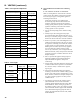
Table 4: Vent Length
Model
3” Vent Pipe
(Equiv. Ft.)
4” Vent Pipe
(Equiv. Ft.)
Min. Max. Min. Max.
PVCG30B &
PVCG40B
8 50 --- ---PVCG50B &
PVCG60B
PVCG70B
PVCG80B &
PVCG90B
--- --- 8 40
III. VENTING (continued)
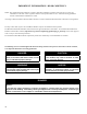
A. Vent Guidelines Due to Removal of an Existing
Boiler
IF AN EXISTING BOILER IS REMOVED -
When an existing boiler is removed from a common
venting system, the common venting system is likely
to be too large for proper venting of the appliances
remaining connected to it.
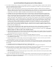
At the time of removal of an existing boiler,
the following steps shall be followed with each
appliance remaining connected to the common
venting system placed in operation, while the other
appliances remaining connected to the common
venting system are not in operation:
1. Seal any unused openings in the common venting
system.
2. Visually inspect the venting system for proper
size and horizontal pitch and determine there is no
blockage or restriction, leakage, corrosion, and other
deciencies which could cause an unsafe condition.
3. Insofar as is practical, close all building doors and
windows and all doors between the space in which
the appliances remaining connected to the common
venting system are located and other spaces of the
building. Turn on clothes dryers and any appliance
not connected to the common venting system.
Turn on any exhaust fans, such as range hoods and
bathroom exhausts, so they will operate at maxi mum
speed. Do not operate a summer exhaust fan. Close
replace dampers.
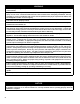
4. Place in operation the appliance being inspected.
Follow the Lighting (or Operating) Instructions.
Adjust thermo stat so appliance will operate
continuously.
5. Test for spillage at the draft hood relief opening after
5 minutes of main burner operation. Use the ame
of a match or candle, or smoke from a cigarette,
cigar or pipe.
6. After it has been determined that each appliance
remain ing connected to the common venting system
properly vents when tested as outlined above, return
doors, win dows, exhaust fans, replace dampers and
any other gas burning appliance to their previous
conditions of use.
7. Any improper operation of the common venting
system should be corrected so the installation
conforms with the National Fuel Gas Code, ANSI
Z223.1/NFPA 54. When resizing any portion of
the common venting system, the common venting
system should be resized to approach the minimum
size as determined using the appropriate tables in
Chapter 13 of the National Fuel Gas Code, ANSI
Z223.1/NFPA 54.