
Install Instructions

34
V: SYSTEM START-UP (continued)
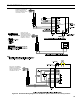
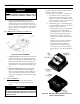
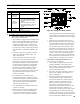
Figure 26: Adjusting Fuel Pump Pressure
4. Adjust oil pressure.
a. When checking a fuel unit's operating pressure, a
reliable pressure gauge may be installed in either
the bleeder port or the nozzle port. Refer to
Figure 26. Refer to Figure 9 for Riello burner.
b. Locate oil pressure adjusting screw and turn
screw to obtain proper pump pressure, refer to
Tables 14A and 14B at the rear of this manual.
c. To check the cutoff pressure, deadhead a reliable
pressure gauge onto the copper connector tube
attached to the nozzle port. Run the burner for
a short period of time. Shut the burner off. The
pressure should drop and hold.
d. Remove the gauge and install bleeder port and/or
reconnect the nozzle port line.
G. ADJUST OIL BURNER WHILE OPERATING.
(FLAME PRESENT)
1. Set room thermostat about 10°F below room
temperature.
2. Press red reset button on Oil Primary Control and
release.
3. Beckett Burners - Readjust the head setting, only if
necessary.
a. CL3-091 thru CL4-126:
Beckett MB(L1) Head burners have a xed head
which are non-adjustable.
b. CL4-175 thru CL5-280:
Beckett MD(V1) (variable) Head burners have
the ability to control air by moving the head. It
might be necessary to move the head forward
or back one position at a time to optimize the
smoke and CO
2
readings. See Figure 27 and
Table 14A at the rear of this manual.
4. Riello Burners - Readjust the turbulator setting,
only if necessary.
a. CL3 through CL5 (All Models)
Move the turbulator setting forward or back one
position at a time to optimize the smoke and
CO2 readings. Refer to Figure 8 and Table 14B
at the rear of this manual.
5. Readjust the Head Setting, only if necessary.
a. Carlin EZ-1HP and EZ-2HP burners use a head
positioning bar to x the head setting based
on nozzle size. To adjust this setting, bar must
be changed to the next larger or smaller bar
available.
6. Readjust the Air Damper Setting (air Band/Air
Shutter/Air Gate) on the burner for a light orange
colored ame while the draft over the re is -0.02”.
Use a smoke tester and adjust air for minimum
smoke (not to exceed #1) with a minimum of excess
air. Make nal check using suitable instrumentation
to obtain a CO
2
of 11.5 to 12.5% with draft of -0.02”
(water gauge) in re box. These settings will assure
a safe and efcient operating condition. If the ame
appears stringy instead of a solid re, try another
nozzle of the same type. Flame should be solid and
compact. After all adjustments are made, recheck
for a draft of -0.02” over the re.
7. Only Readjust the Head/Turbulator Setting, if
necessary.
a. CL3 through CL5 (All Models)
Move the setting forward or back one position at
a time to optimize the smoke and CO
2
readings.
b. Steps outlined in Paragraph 5 and 6 above must
be repeated every time the Head/Turbulator or
Air Damper Setting is readjusted.
8. Turn “OFF” burner and remove Riello
Combination Pressure Gauge and Bleeder Valve
Assembly. Install pressure port/bleeder plug and
tighten. Start burner again.
WARNING
DO NOT loosen or remove any oil line ttings
while burner is operating.
9. Flame Failure
The CL boiler controls operate the burner
automatically. If for unknown reasons the burner
ceases to re and the reset button on the primary
control has tripped, the burner has experienced
ignition failure. Refer to Oil Primary Control
features, Paragraph I, Step 2 of this Section and
Section IX, Troubleshooting, Paragraph B. If
the failure re-occurs, call your heating contractor
immediately before pressing the reset button.