
Install Instructions

33
3. Steam Boilers:
With an PA404A Pressure Limit - set cut-out
pressure (MAIN scale) on the pressure limit for
(1) PSI and differential pressure (DIFF.) for .5 PSI.
These pressures may be varied to suit individual
requirements of the system.
4. Steam Boilers with Tankless Domestic Water
Heaters, set boiler water temperature dial on L4006
operating control at 190°F (max.). Set differential at
10°.
5. Water Boilers without Tankless Heaters, are
equipped with an Intelligent Oil Boiler Control
(Boiler Control). The Boiler Control is factory
programmed with a High Limit setpoint of 180°F.
The High Limit setpoint is adjustable between
140°F and 240°F. This temperature may be varied
to suit the installation requirements.
High Limit Differential is factory programmed at
15°F and is adjustable between 10°F and 30°F.
6. Water Boilers with Tankless Heaters are equipped
with a Warm Start Intelligent Oil Boiler Control
(Warm Start Boiler Control). The Warm Start
Boiler Control is factory programmed with a High
Limit setpoint of 180°F. The High Limit setpoint
is adjustable between 140°F and 240°F. High
Limit Differential is factory programmed at 10°F.
Additionally, the Warm Start Boiler Control is
factory programmed with a Low Limit setpoint
of 110°F. The Low Limit setpoint is adjustable
between 110°F and 220°F. These temperatures may
be varied to suit the installation requirements.
7. Checkout
Put the system into operation and observe at least
one complete cycle to make sure that the controller
operates properly. See Troubleshooting Section to
use LED to assist in determining system operation.
E. ADJUST OIL BURNER BEFORE STARTING.
1. Check Burner Settings and readjust if necessary,
see Burner Specications, Tables 14A and 14B at
rear of this manual.
2. Beckett Burners
a. Inspect Beckett head setting on left side of
burner housing by insuring the blue line MD(V1)
or the line on the label MB(L1) are aligned,
readjust if necessary. Refer to Figure 27 and
Table 14A at the rear of this manual.
b. Check burner air band and air shutter settings.
Readjust if necessary, see Burner Specications
Table 14A at the rear of this manual.
c. Open all oil line valves.
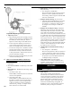
d. Attach a plastic hose to fuel pump vent tting
and provide a pan to catch the oil.
V: SYSTEM START-UP (continued)
e. Open Flame Observation Port cover on burner
swing door.
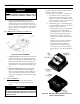
3. Riello Burners
a. Inspect Riello head setting on left side of burner
by reading the scale embossed on the housing
cover. Refer to Figure 8.
b. Inspect Riello burner air damper and turbulator
setting. Readjust if necessary, see Table 14B at
the rear of this manual.
c. OPEN ALL OIL LINE VALVES.
d. Provide a pan to catch oil.
e. Remove pressure port/bleeder plug from fuel
pump and install Riello Combination Pressure
Gauge and Bleeder Valve Assembly.
f. OPEN FLAME OBSERVATION PORT COVER
on burner swing door.
CAUTION
Air Band is set for maximum input and must be
readjusted prior to starting burner, if nozzle was
changed to a lower ring rate.
4. Carlin Burners
a. Inspect Carlin head setting on left side of burner
to ensure that the proper head positioning bar
matches the nozzle that is installed in drawer
assembly. Replace bar if necessary.
b. Change the factory air settings according to
Table 14C (at rear of this manual)
c. Open all oil line valves.
d. Attach a plastic hose to fuel pump vent tting
and provide a pan to catch the oil.
e. Open ame ovservation port cover on burner
swing door.
F. START OIL BURNER.
1. Open vent tting on fuel pump.
2. Turn 'ON' Burner service switch and allow burner
to run until oil ows from vent tting in a solid
stream without air bubbles for approximately 10
seconds.
3. Close vent tting and burner ame should start
immediately after prepurge is completed. Prepurge
prevents burner ame until 10 seconds has elapsed
after initial power is applied to burner. During
prepurge the motor and igniter will operate but the
oil valve will remain closed. Refer to Oil Primary
Control Instructions for more details.