INSTALLATION, OPERATING AND SERVICE INSTRUCTIONS CL™ SERIES CAST IRON OIL-FIRED BOILER 9700609 For service or repairs to boiler, call your heating contractor. When seeking information on boiler, provide Boiler Model Number and Serial Number as shown on Rating Label. Boiler Model Number CL Heating Contractor Boiler Serial Number Installation Date Phone Number Address 103876-06 - 4/16 Price - $5.
IMPORTANT INFORMATION - READ CAREFULLY All boilers must be installed in accordance with National, State and Local Plumbing, Heating and Electrical Codes and the regulations of the serving utilities. These Codes and Regulations may differ from this instruction manual. Authorities having jurisdiction should be consulted before installations are made. In all cases, reference should be made to the following Standards: USA BOILERS A.
DANGER DO NOT store or use gasoline or other flammable vapors or liquids in the vicinity of this or any other boiler. WARNING Improper installation, adjustment, alteration, service or maintenance can cause property damage, personal injury or loss of life. Failure to follow all instructions in the proper order can cause personal injury or death.
WARNING This boiler contains very hot water under 12 - 15 PSI pressure. Do not unscrew any pipe fittings nor attempt to disconnect any components of this boiler without positively assuring the water is cool and has no pressure. Always wear protective clothing and equipment when installing, starting up or servicing this boiler to prevent scald injuries. Do not rely on the pressure and temperature gauges to determine the temperature and pressure of the boiler.
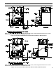
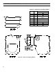
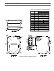
I: GENERAL INFORMATION 'B' 'C' DIA. NOTE: For Carlin Burners Only: Burner extends in front of boiler 11-1/4", burner swing door clearance is 10", burner extends 2-5/8" above floor and burner is not available with cover. Figure 1A: CL3 Thru CL5 Water Boiler without Tankless Heater, All Burner Options NOTE: For Carlin Burners Only: Burner extends in front of boiler 11-1/4", burner swing door clearance is 10", burner extends 2-5/8" above floor and burner is not available with cover.
I: GENERAL INFORMATION (continued) 'A' 'B' 'C' DIA. NOTE: For Carlin Burners Only: Burner extends in front of boiler 11-1/4", burner swing door clearance is 10", burner extends 2-5/8" above floor and burner is not available with cover.
I: GENERAL INFORMATION (continued) TABLE 1: DIMENSIONAL DATA / general information (See figures 1a thru 1C) Dimensions "A" "B" "C" Approx. Water Content - Gallons CL3 17-3/8" 8-1/4" 5-7/8" 16 14.33 CL4 22-3/8" 10-7/8" 6-7/8" 20 20.90 CL5 27-3/8" 13-3/8" 7-7/8" 24 27.46 Boiler Series Heat Transfer Surface Area - Sq. Ft.
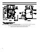
I: GENERAL INFORMATION (continued) Table 3A: Purpose of Tappings (Water) Tapping Location Size, NPT A 1½” B ½” C ¼” D 1½” Supply E 1½” Optional Return Return Limit Well Plug Temperature/Pressure Gauge F ¾” G ¾” N/A H ¾” N/A Limit Well I ¾” N/A DHW Inlet Figure 2A: Purpose of Tappings (Water) 8 Purpose Less Heater With Heater Relief Valve DHW Outlet
I: GENERAL INFORMATION (continued) Table 3B: Purpose of Tappings (Steam) Purpose Tapping Size, Location NPT Less Heater With Heater A B C D E F G H I J K L M N O P 1½” ½” ¼” 3” 1½” ¾” ¾” ¾” ¾” ¾” ¾” ½” ½” 1” ½” 1½” Return Pressure Limit Pressure Gauge Supply Optional Return Relief Valve N/A DHW Outlet N/A Limit Well N/A DHW Inlet Drain LWCO Water Gauge Glass Water Gauge Glass Indirect Water Heater Supply Indirect Water Heater Limit Surface Blowoff Figure 2B: Purpose of Tappings (Steam) 9
II: Pre-Installation A. INSPECT SHIPMENT carefully for any signs of damage. 1. All equipment is carefully manufactured, inspected and packed. Our responsibility ceases upon delivery of crated boiler to the carrier in good condition. 2. Any claims for damage or shortage in shipment must be filed immediately against the carrier by the consignee. No claims for variances from, or shortage in orders, will be allowed by the manufacturer unless presented within sixty (60) days after receipt of goods. B.
II: Pre-Installation (continued) C. PROVIDE COMBUSTION AND VENTILATION AIR. Local and National Codes may apply and should be referenced. WARNING Adequate combustion and ventilation air must be provided to assure proper combustion and to maintain safe ambient air temperatures. Do not install boiler where gasoline or other flammable vapors or liquids, or sources of hydrocarbons (i.e. bleaches, fabric softeners, etc.) are used or stored. 1. Determine volume of space (boiler room).
III: Installation Instructions A. REMOVE CRATE. 1. Remove all fasteners at crate skid. 2. Lift outside container and remove all other inside protective spacers and bracing. Remove miscellaneous steam or water trim carton. B. REMOVAL OF BOILER FROM SKID. 1. Boiler is secured to base with 4 carriage bolts, 2 on left side and 2 on right side. See Figure 4. Remove all bolts. CAUTION Do not install burner without Gasket. 3.
III: Installation Instructions (continued) h. Reinstall Beckett MB(L1) or MD(V1) Head. i. Inspect and measure burner electrodes. Refer to Figure 27 for the proper electrode setting. Readjust electrode setting to the proper dimensions if necessary. Refer to Figure 27. j. Reinstall nozzle line electrode assembly. k. Connect copper connector tube. l. Inspect Beckett head setting on left side of burner by insuring the line on the label MB(L1) or the blue line MD(V1) are aligned, readjust if necessary.
III: Installation Instructions (continued) 4. On the Carlin EZ-PH Burner, use the following procedure to complete the inspection, check the settings and to change the nozzle to a lower firing rate: Figure 8: Riello Turbulator Setting This burner is shipped with the oil pump set to operate on a single line system. To operate on a two-line system the bypass plug must be installed. WARNING: Do not operate a single line system with the by-pass plug installed.
III: Installation Instructions (continued) Figure 10: Electrode Settings k. l. m. n. Reinstall nozzle line electrode assembly. Reconnect copper connector tube. Tighten knurled nut. Close igniter, rotate and tighten two (2) igniter latching screws. b. On water boilers with rear tankless heater, the factory wired Warm Start Boiler Control was not installed in heater. Locate 3/4" NPT immersion well, apply sealant, thread into 3/4" NPT tapping on tankless heater and tighten with wrench.
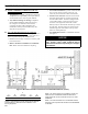
Figure 12A: Recommended Water Piping for Circulator Zoned Heating System - Supply Side Circulator III: Installation Instructions (continued)
Figure 12B: Recommended Water Piping for Zone Valve Zoned Heating System - Supply Side Circulator III: Installation Instructions (continued)
Figure 13: Recommended Boiler Piping for Gravity Return Steam Boiler III: Installation Instructions (continued)
III: Installation Instructions (continued) 4. Connect Field Wiring a. Connect the field wiring to the pressure limit, the LWCO and the burner or primary control. If equipped with tankless heater, connect field wiring from the Aquastat Control to the Oil Primary Control "TT" terminals. Make the wiring connections as shown in Figure 23. Note: • The GeniSys 7505 Oil Primary Control has pre-installed "T-T" jumper. To activate "T-T" terminals, "T-T" jumper must be removed.
III: Installation Instructions (continued) iii. Eliminating and/or repairing fittings which allow oxygen absorption. iv. Use of non-permeable materials in the distribution system. v. Isolating the boiler from the system water by installing a heat exchanger. e. A hot water boiler installed above radiation level must be provided with a low water cutoff device as part of the installation. See Appendix A, Low Water Cut-Off for additional details. 3. Steam Boiler a.
III: Installation Instructions (continued) The following guidelines should be followed when piping the tankless heater: 1. Flow Regulation — If flow through the heater is greater than its rating, the supply of adequate hot water may not be able to keep up with the demand. For this reason a flow regulator matching the heater rating should be installed in the cold water line to the heater.
III: Installation Instructions (continued) Figure 16: Indirect Water Heater Piping on CL Series Steam Boiler WARNING Vent this boiler according to these instructions. Failure to do so may cause products of combustion to enter the home resulting in severe property damage, personal injury or death. Insufficient Combustion Air Supply may result in the production and release of deadly carbon monoxide (CO) into the home which can cause severe personal injury or death.
III: Installation Instructions (continued) b. Unlined Chimney – Under no circumstances shall a chimney constructed of brick only be used. Only approved clay liners or listed chimney lining systems shall be used as specified in NFPA 31 or CSA B139. c. Abandoned Openings – Openings through the chimney wall that are no longer used shall be sealed in accordance to NFPA 211. Often abandoned openings are improperly sealed and usually covered by a gypsum wall covering. d.
III: Installation Instructions (continued) a. Type L or a factory built chimney material that complies with the Type HT requirements of ANSI/UL 103. Install in accordance with listing and manufacturer’s instructions. b. Steel pipe having resistance to corrosion and heat with a minimum wall thickness of 24 Gauge (0.024”). DANGER Any signs of condensate seepage at the base of the chimney shall be inspected immediately. The discoloration may be a sign of chimney damage and must be remedied immediately.
III: Installation Instructions (continued) Table 5: single stage units (3450 rpm) two pipe systems Lift "H" (See Figure) 0' 1' 2' 3' 4' 5' 6' 7' 8' 9' 10' 11' 12' 13' 14' Maximum Length of Tubing "H" + "R" (See Figure) 3/8" OD 1/2" OD Tubing (3 GPH) Tubing (3 GPH) 84' 78' 73' 68' 63' 57' 52' 47' 42' 36' 31' 26' 21' ----- 100' 100' 100' 100' 100' 100' 100' 100' 100' 100' 100' 100' 83' 62' 41' Table 6: two-stage units (3450 rpm) two-pipe systems Lift "H" (See Figure) Maximum Length of Tubing "H" + "R" (Se
IV: Electrical DANGER Positively assure all electrical connections are unpowered before attempting installation or service of electrical components or connections of the boiler or building. Lock out all electrical boxes with padlock once power is turned off. WARNING Failure to properly wire electrical connections to the boiler may result in serious physical harm. Electrical power may be from more than one source. Make sure all power is off before attempting any electrical work.
Figure 21: Schematic Wiring Diagram, without Tankless Heater, Cold Start Control (All Burners) IV: Electrical (continued) Refer to Figure 25 for Schematic wiring diagram of appropriate burner and oil primary control option
Figure 22: Schematic Wiring Diagram, with Tankless Heater, Warm Start Control (All Burners) IV: Electrical (continued) Refer to Figure 25 for Schematic wiring diagram of appropriate burner and oil primary control option
N 1 2 1-3 BK WH Jumper Figure 23: Schematic Wiring Diagram, Steam Boilers With or Without Tankless Heater, McDonnell & Miller PSE-801 Probe LWCO, Beckett AFG and Carlin EZ Burners H-C B H 5 RD Lettered Terminals Numbered Terminals Wire Color McDonnell & Miller PSE-801 Terminals May Be Lettered or Numbered as Follows: Refer to Figure 25 for Schematic wiring diagram of appropriate burner and oil primary control option IV: Electrical (continued)
Refer to Figure 25 for Schematic wiring diagram of appropriate burner and oil primary control option Figure 24: Schematic Wiring Diagram, Water Boilers with or without Tankless Heater, Hydrolevel HydroStat, All Burners IV: Electrical (continued)
IV: Electrical (continued) NOTE: APPLY THIS BURNER SCHEMATIC TO APPROPRIATE STEAM OR WATER BOILER CONTROL SCHEMATIC, REFER TO Figures 21 THRU 24 NOTE: APPLY THIS BURNER SCHEMATIC TO APPROPRIATE STEAM OR WATER BOILER CONTROL SCHEMATIC, REFER TO Figures 21, 22 and 24 NOTE: APPLY THIS BURNER SCHEMATIC TO APPROPRIATE STEAM OR WATER BOILER CONTROL SCHEMATIC, REFER TO Figures 21 THRU 24 Figure 25: Schematic Wiring Diagrams For All Burner Options w/Various Oil Primary Controls 31
V: system start-up WARNING All boilers equipped with burner swing door have a potential hazard which can cause severe property damage, personal injury or loss of life if ignored. Before opening swing door, turn off service switch to boiler to prevent accidental firing of burner outside the combustion chamber. Be sure to tighten swing door fastener completely when service is completed. A. ALWAYS INSPECT INSTALLATION BEFORE STARTING BURNER. 1.
V: system start-up (continued) 3. Steam Boilers: With an PA404A Pressure Limit - set cut-out pressure (MAIN scale) on the pressure limit for (1) PSI and differential pressure (DIFF.) for .5 PSI. These pressures may be varied to suit individual requirements of the system. 4. Steam Boilers with Tankless Domestic Water Heaters, set boiler water temperature dial on L4006 operating control at 190°F (max.). Set differential at 10°. 5.
V: system start-up (continued) 4. Riello Burners - Readjust the turbulator setting, only if necessary. a. CL3 through CL5 (All Models) Move the turbulator setting forward or back one position at a time to optimize the smoke and CO2 readings. Refer to Figure 8 and Table 14B at the rear of this manual. 5. Readjust the Head Setting, only if necessary. a. Carlin EZ-1HP and EZ-2HP burners use a head positioning bar to fix the head setting based on nozzle size.
Figure 27: "L1" and "V1" Head Electrode Positioning and Gun Setting (Beckett AFG) V: system start-up (continued)
V: system start-up (continued) WARNING Do not attempt to start the burner when excess oil has accumulated, when the boiler is full of vapor, or when the combustion chamber is very hot. 10. Cad Cell Location and Service. The burner is supplied with a cadmium sulfide flame detector mounted at the factory, mounted on the bottom of the electronic ignitor. See Figure 28. To service cad cell or to replace the plug in portion, swing open the ignitor. After service is complete, be sure to fasten down the ignitor.
V: system start-up (continued) • At the end of four (4) minutes, the yellow light will turn off and the control will automatically return to standby mode. iii. Limited Recycle: This feature limits the number of recycle trials (for each call for heat) to a maximum of three trials. If the flame is lost three times and does not successfully satisfy a call for heat, the 7505 locks out. iv.
V: system start-up (continued) • Device tries to restart system after approximately 60 seconds. • After third Recycle Mode trial, safety switch locks out within safety switch timing indicated on label and control enters Restricted Mode. Ignition and motor stop and oil valves closes. d. Power Failure Check: After Flame is established, turn the power off to the control/ burner. The burner should shut down safely. When power is restored a normal ignition sequence should be started.
VI: OPERATING Table 7: sequence of operation Status Codes Displayed in Mode Status Description Standby (burner off, pump off) No call for heat detected Standby (burner off, pump on) Either condition is true: a. Call for heat detected and boiler temperature higher than operating setpoint. b. Call for heat detected and boiler temperature higher than 140 F and Pump Pre-Purge Time has not expired. Running The burner runs until the call for heat is satisfied.
VI: OPERATING (continued) d. If the thermostat is not satisfied and the Operating Setpoint (SP) is reached the system circulator will continue to operate and the burner will stop. When the boiler water temperature drops below the setpoint less the differential setting the burner will restart. e. After the thermostat is satisfied the burner and circulator are stopped. f. The Warm Start Boiler Control also includes a low limit control function.
VI: OPERATING (continued) Cold Start Boiler Control Adjustment Mode Options HL_ HdF ZC_ Or_ PP_ St_ Pt_ f-C bac 140-240°F 10-30°F dh, ZR or ELL 0-10 minutes 2-20 minutes 140 - 180°F On or Off F or C Adjust High Limit Setting Adjust High Limit Differential ZC and ZR Terminal Function Pump Overrun Time Pump Pre-purge Time Start Temperature Priority Time Select degrees F or C Mode Back to Operating Mode Warm Start Boiler Control Adjustment Mode Options HL_ LL_ 140-240°F 110-220°F Ldf 10-25°F ZC_ Or_ P
VI: Operating (continued) terminal for the DHW Circulator. When there is a DHW call for heat, the System Circulator is “forced off”, the DHW Circulator terminal is energized and the circulator pre-purge time delay control logic is bypassed to allow the boiler to fire without delay. When DHW demand ends the System Circulator “force off” is removed, the circulator can respond normally, and the DHW Circulator is deenergized. The DHW call for heat is detected by a voltage on to the "ZR" terminal.
VI: Operating (continued) Table 10: zone request, parameter zc_= zr Call for Heat T-T ZR Input Input off on on off off off on on Circulator Status C1 ZC Output Output off on on off off off on on Table 11: External low limit, parameter zc_= ell Call for Heat T-T ZR Input Input off on on off iii.
VII: Maintenance and Service Instructions A. MAINTENANCE OF LOW WATER CUT-OFF DEVICES WARNING Probe and float type low water cut-off devices require annual inspection and maintenance. 1. Although these devices are solid state in their operation, the probe is exposed to possible contamination in the boiler water and subject to fouling. 2. It is important to physically remove the probe from the boiler tapping annually and inspect that probe for accumulation of scale or sediment. 3.
VII: Maintenance and Service Instructions (continued) NOTICE Check with local authorities or consult local water treatment services for acceptable chemical cleaning compounds. iii. Start burner and operate sufficiently to boil the water without producing steam pressure. Boil for about 5 hours. Open boiler feed pipe sufficiently to permit a steady trickle of water from the surface blow-off pipe.
VII: Maintenance and Service Instructions (continued) 2. Water Boilers: a. Filling of boiler and system. General — In a hot water heating system, the boiler and entire system (other than the expansion tank) must be full of water for satisfactory operation. Water should be added to the system until the boiler pressure gauge registers 12 psi. To insure that the system is full, water should come out of all air vents when opened. b. Boiling out of boiler and system.
VII: Maintenance and Service Instructions (continued) again to proper level. If, at this time, boiler water is dirty, drain water, flush out boiler, and refill with clean water to prescribed water level. 4. Always keep the manual fuel supply valve shut off if the burner is shut down for an extended period of time. 5. To recondition the heating system in the fall season after a prolonged shut down, follow the instructions outlined in Section V, Paragraphs A through K.
VIII: Boiler Cleaning (continued) Figure 32: Cleaning of Boiler Flueways 48
Important Product Safety Information Refractory Ceramic Fiber Product Warning: The Repair Parts list designates parts that contain refractory ceramic fibers (RCF). RCF has been classified as a possible human carcinogen. When exposed to temperatures above 1805°F, such as during direct flame contact, RCF changes into crystalline silica, a known carcinogen. When disturbed as a result of servicing or repair, these substances become airborne and, if inhaled, may be hazardous to your health.
IX: Troubleshooting A. COMBUSTION 1. Nozzles — Although the nozzle is a relatively inexpensive device, its function is critical to the successful operation of the oil burner. The selection of the nozzle supplied with the CL boiler is the result of extensive testing to obtain the best flame shape and efficient combustion. Other brands of the same spray angle and spray pattern may be used but may not perform at the expected level of CO2 and smoke.
IX: Troubleshooting (continued) B. OIL PRIMARY CONTROL (Oil Primary) 1. Burner (Oil Primary) will not come on. a. No power to Oil Primary. b. Oil Primary is in lockout or restricted mode. Press reset button for one (1) second to exit lockout. If control has recycled three times within the same call for heat, it will enter into restricted mode. To reset from restricted mode, refer to Section V, Paragraph I, Step 2 for details. c. CAD cell seeing light. d. CAD assembly defective. e.
IX: Troubleshooting (continued) Table 12: Troubleshooting guide System Condition Diagnostic Condition Check Action Boiler is cold, house is cold. Display is OFF. 120 Vac System power. Display is ON. 24 Vac T-T Turn system power on. No 24 V; replace control. 24 V present; disconnect thermostat, short T-T. 120 Vac at B1-B2 Boiler starts, check wiring and thermostat. • If no, replace control. • If yes, check burner and wiring. Refer to Err on display. Boiler is hot, house is cold. Display is ON.
X: Repair Parts All CL™ Series repair parts may be ordered through New Yorker Boiler Company, Inc., or its authorized distributors. Should you require assistance in locating a New Yorker Distributor in your area, or have questions regarding the availability of New Yorker products or repair parts, please contact: New Yorker Boiler Company, Inc., P.O. Box 10, Hatfield, PA 19440-0010, Attn: Customer Service Department. Visit our website at www.newyorkerboiler.
X: Repair Parts (continued) Bare Boiler Assembly (Exploded View)
X: Repair Parts (continued) Item No. Description Boiler Size / Quantity Part No.
X: Repair Parts (continued) Jacket Assembly (Exploded View) Item No. Boiler Size / Quantity Description CL3 Part No.
X: Repair Parts (continued) CL3 Thru CL5 Water Boilers - Trim and Controls Item Description No. CL3 Thru CL5 Water Boilers - Trim and Controls 1 2a 2b 3a 3b 4 5 6 7 8 9 10 11 12 13 14 Beckett GeniSys 7505B Oil Primary Control Honeywell L7248L1090 Hi Limit, Circ. Relay (WL) Honeywell L7224C1010 Hi & Lo Limit, Circ.
X: Repair Parts (continued) CL3 Thru CL5 Steam Boilers - Trim and Controls Item No. Description Boiler Size / Quantity CL3 CL4 CL5 Part No.
X: Repair Parts (continued) Beckett AFG Burner
BECKETT AFG OIL BURNER PART NOS. FOR CL SERIES BOILERS NOTE: When ordering parts always give the serial and model numbers shown on the boiler and burner. Also provide the name of the part(s) and part number as listed below.
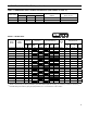
XI: Burner Specifications Table 14A: Beckett Afg Burner Specifications Beckett AFG Boiler Series 1 CL3-091 CL3-105 p CL3-140 Firing Rate GPH 0.65 0.75 L1 1.00 CL4-126 0.90 CL4-175 1.25 CL4-210 Settings Head Air (Setting) Shutter 1.50 L1 V1(0) Nozzle 3 Air Band GPH x Angle Type 2 8 0 0.55 x 70B (Delavan) p Loose 10 2 0.65 x 60B (Hago) p Loose 5 2 0.85 x 60B (Hago) Installed 7 0 0.75 x 60B (Delavan) Installed 10 0.5 1.00 x 60B (Hago) 10 6 1.
XI: Burner Specifications (continued) RIELLO 40 Series OIL BURNER PART NUMBERS FOR CL SERIES BOILERS Table 14B: Riello Burner Specifications 2 Boiler Series Firing Rate GPM CL3-105 0.75 CL3-140 1.00 CL4-126 0.90 CL4-175 CL4-210 Settings Burner Model Air Gate Turbulator Nozzle GPH x Angle Type 2 Shipped Pump Pressure 2.60 0 0.60 x 60A (Delavan) Installed 2.85 2 0.85 x 60W (Delavan) Loose 40F5 2.25 0 0.75 x 60B (Delavan) Installed 1.25 40F5 4 4 1.
XI: Burner Specifications (continued) CARLIN OIL BURNER PART NUMBERS FOR CL SERIES BOILERS NOTE: When ordering parts always give the serial and model numbers shown on the boiler and burner. Refer to Carlin Model EZ-1/2/3 Oil Burner-Instruction Manual (Form #MNEZ123) for an exploded view of the burner and a list of spare parts. For replacement Carlin oil burner parts, contact your wholesaler or the burner manufacturer: CCT, Carlin Combustion Technology, Inc.
Appendix A - AFTERMARKET Low Water Cut Off (LWCO) WARNING DO NOT ATTEMPT to cut factory wires to install an aftermarket Low Water Cut Off (LWCO). Only use connections specifically identified for Low Water Cut Off. In all cases, follow the Low Water Cut Off (LWCO) manufacturer's instructions. When A low water cutoff is required to protect a hot water boiler when any connected heat distributor (radiation) is installed below the top of the hot water boiler (i.e.
Appendix A - AFTERMARKET Low Water Cut Off (LWCO) (continued) How to Test Shut off fuel supply. Close shut-off valves in system supply and return piping located in near boiler piping above LWCO as shown in Figure A1. Open drain valve to lower water level until water is below the LWCO probe. It may be necessary to open relief valve seat to allow air into system for the water to drain, close drain valve and relief valve once completed. Generate a boiler demand by turning up thermostat.
NEW YORKER BOILER COMPANY, INC. Limited Warranties For Residential Cast Iron and Steel Boilers By this Warranty Statement New Yorker Boiler Company, Inc. (“New Yorker”), issues limited warranties subject to the terms and conditions stated below. These limited warranties apply to residential cast iron and steel water boilers labeled with the New Yorker® brand which are sold on or after March 1, 2004.