
User Guide


25
103876-08 - 1/19
CL
Installation & Service Manual
Lift "H"
(See Figure)
Maximum Length of Tubing
"H" + "R" (See Figure)
3/8" OD
Tubing (3 GPH)
1/2" OD
Tubing (3 GPH)
0' 93' 100'
2' 85' 100'
4' 77' 100'
6' 69' 100'
8' 60' 100'
10' 52' 100'
12' 44' 100'
14' 36' 100'
16' 27' 100'
18' --- 76'
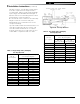
Table 6: Two-Stage Units (3450 rpm)
Two-Pipe Systems
Lift "H"
(See Figure)
Maximum Length of Tubing
"H" + "R" (See Figure)
3/8" OD
Tubing (3 GPH)
1/2" OD
Tubing (3 GPH)
0' 84' 100'
1' 78' 100'
2' 73' 100'
3' 68' 100'
4' 63' 100'
5' 57' 100'
6' 52' 100'
7' 47' 100'
8' 42' 100'
9' 36' 100'
10' 31' 100'
11' 26' 100'
12' 21' 83'
13' --- 62'
14' --- 41'
Table 5: Single Stage Units (3450 rpm)
Two Pipe Systems
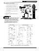
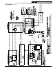
Figure 20: Two Pipe Oil Lines
Two-Pipe Oil Lines - For two-pipe systems where
more lift is required, the two-stage fuel unit is
recommended. Table 5 (single-stage) and Table
6 (two-stage) show allowable lift and lengths of
3/8-inch and 1/2-inch OD tubing for both suction
and return lines. Refer to Figure 20.
Be sure that all oil line connections are absolutely
airtight. Check all connections and joints.
Flared fittings are recommended. Do not use
compression fittings.
Open the air-bleed valve and start the burner. For
clean bleed, slip a 3/16" ID hose over the end
of the bleed valve and bleed into a container.
Continue to bleed for 15 seconds after oil is free
of air bubbles. Stop burner and close valve.
3 Installation Instructions (continued)