
User Guide

14
103876-08 - 1/19
CL Installation & Service Manual
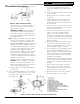
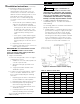
set to operate on a single line system. To
operate on a two-line system the bypass
plug must be installed.
WARNING: DO NOT operate a single line
system with the by-pass plug installed.
Operating a single line system with the by-
pass plug installed will result in damage to
the pump shaft seal.
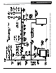
Note: Pump pressure was factory pre-set but
must be checked at time of burner start-
up. A pressure gauge is attached to the
PRESSURE/BLEEDER PORT (7) for pressure
readings. Two PIPE CONNECTORS (4)
are supplied with the burner for connection
to either a single or two-line system. Also
supplied are two ADAPTORS (3), two
female ¼” NPT to adapt oil lines to burner
pipe connectors. All pump port threads
are British Parallel Thread design. Direct
connection of NPT threads to the pump will
damage the pump body.
Riello manometers and vacuum gauges
DO NOT require any adapters, and can be
safely connected to the pump ports. An
NPT x metric adapter must be used when
connecting other gauge models.
h. Replace Burner Cover and Tighten Burner
Cover Screws.
4. On the Carlin EZ-PH Burner, use the following
procedure to complete the inspection, check
the settings and to change the nozzle to a
lower firing rate:
Figure 9: Riello Pump Connections and Port Identification
a. Loosen two (2) igniter latching screws,
rotate tabs and swing open igniter about
hinge.
b. Loosen knurled nut and disconnect copper
connector tube.
c. Remove nozzle line electrode assembly
from burner.
d. If high firing rate is desired, confirm the
nozzle is the proper size and type, refer
to Table 14C (at rear of this manual), then
proceed to Item i.
e. If a lower input is desired, remove the flame
retention head and then remove the nozzle
that was factory installed.
f. Locate the desired nozzle, refer to Table
14C (at rear of this manual) for proper
nozzle. The nozzle must be securely
installed to assure leak free joints between
the nozzle and adapter. When installing the
nozzle, be careful not to bump or move the
burner electrodes.
g. Reinstall Flame Retention Head on Nozzle
Line Electrode Assembly. Make sure the
clamp is fully sated against the shoulder on
the nozzle adapter before securing.
h. Loosen and remove the retaining nut and
factory installed head bar from side of
burner housing. Install the proper head bar
that corresponds to the desired firing rate,
refer to Table 14C (at rear of this manual),
and tighten retaining nut.
i. Readjust air band to preliminary setting that
corresponds to the lower firing rate nozzle
installed, refer to Table 14C (at rear of this
manual).
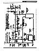
j. Inspect and measure burner electrodes.
Refer to Figure 10 for proper electrode
setting. Readjust electrode setting to the
proper dimensions if necessary.
k. Reinstall nozzle line electrode assembly.
l. Reconnect copper connector tube.
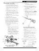
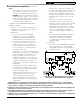
Figure 8: Riello Turbulator Setting
3 Installation Instructions (continued)