
Install Instructions


9
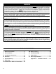
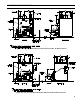
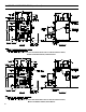
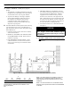
Figure 2B: Purpose of Tappings (Steam)
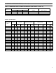
TABLE 3B: PURPOSE OF TAPPINGS (STEAM)
Tapping
Location
Size,
NPT
Purpose
Less Heater With Heater
A 1½” Return
B ½” Pressure Limit
C ¼” Pressure Gauge
D 3” Supply
E 1½” Optional Return
F ¾” Relief Valve
G ¾” N/A DHW Outlet
H ¾” N/A Limit Well
I ¾” N/A DHW Inlet
J ¾” Drain
K ¾” LWCO
L ½” Water Gauge Glass
M ½” Water Gauge Glass
N 1” Indirect Water Heater Supply
O ½” Indirect Water Heater Limit
P 1½” Surface Blowoff
I: GENERAL INFORMATION (continued)