
User Guide


15
103876-08 - 1/19
CL
Installation & Service Manual
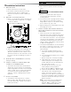
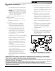
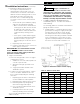
Figure 11: Limit Sensor Insertion
m. Tighten knurled nut.
n. Close igniter, rotate and tighten two (2)
igniter latching screws.
G. INSTALL WATER BOILER TRIM AND CONTROLS,
(see Figures 1A and 1B).
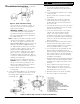
1. Install return piping supplied with boiler. Apply
Teflon or Sealant to all joints prior to assembly.
Thread 1½" NPT x 5" Lg. return nipple into 1½"
NPT tapping located in lower left corner of
front section. Thread 1½" x ¾" x 1½" NPT tee
onto 5" nipple. Thread ¾" drain valve into ¾"
NPT connection on tee. Tighten all joints with
wrench until water tight and 1½" NPT return
connection on tee is facing away from boiler
horizontally to allow for proper burner swing
door clearance, see Figures 1A, 1B, 12A and
12B.
Note: Vertical piping will prevent door from
opening fully for service and cleaning of boiler.
2. Thread relief valve onto factory installed ¾"
NPT x 7¼" nipple located in left rear corner
on top of boiler as shown in Figures 1A and
1B. Valve spindle must be in vertical position.
Tighten with wrench. Pipe discharge as shown
in Figures 12A and 12B. Installation of the
relief valve must be consistent with ANSI/ASME
Boiler and Pressure Vessel Code, Section IV.
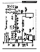
3. Connect Field Wiring
Connect the field wiring to the Warm or Cold
Start Intelligent Oil Boiler Control (Boiler
Control). Make the wiring connections as
shown in Figure 21 and 22.
a. On water boilers without rear tankless
heater, connect the field wiring from the
circulator to the Cold Start Boiler Control
and from the Cold Start Boiler Control to the
Burner Oil Primary Control. Make the wiring
connections as shown on Figure 21.
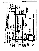
b. On water boilers with rear tankless heater,
the factory wired Warm Start Boiler Control
was not installed in heater. Locate 3/4" NPT
immersion well, apply sealant, thread into
3/4" NPT tapping on tankless heater and
tighten with wrench. Apply heat transfer
paste (not furnished) to limit sensor and
fully insert limit sensor into immersion well
such that the tip on the limit sensor touches
the bottom of the immersion well. See
Figure 11. Tighten clamp screws to secure
Warm Start Boiler Control to immersion well.
Secure Boiler Control conduit to jacket right
side panel with 5/8" cable clamp provided,
refer to Figure 1B. Make the wiring
connections as shown on Figure 22.
H. INSTALL STEAM BOILER TRIM AND CONTROLS,
(see Figure 1C).
1. Thread ¾" MPT safety valve and ¾" NPT
coupling onto factory installed ¾" NPT x
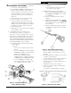
Figure 10: Electrode Settings
7¼" nipple located in left rear corner on top
of boiler as shown in Figure 1C. Tighten
with wrench. Pipe discharge as shown in
Figure 13. Installation of the relief valve must
be consistent with ANSI/ASME Boiler and
Pressure Vessel Code, Section IV.
2. Install ¾" drain valve in wet return piping as
shown in Figure 13.
3. On boilers with rear tankless heater, factory
wired L4006A Aquastat Heater Control was not
installed in heater. Locate ¾" NPT Immersion
Well, apply sealant and thread into ¾" NPT
tapping on heater. Apply heat transfer paste
(not furnished) to control bulb and insert bulb
into immersion well. Tighten clamping screws
to secure Boiler Control to immersion well.
Secure 18/2 Control Cable Wire to jacket right
side panel with 5/16" cable clamp provided,
refer to Figure 1C.
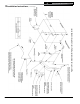
4. Connect Field Wiring
a. Connect the field wiring to the pressure
limit, the LWCO and the burner or primary
control. If equipped with tankless heater,
connect field wiring from the Aquastat
Control to the Oil Primary Control "TT"
terminals. Make the wiring connections as
shown in Figure 23.
3 Installation Instructions (continued)