
User Guide


36
103876-08 - 1/19
CL Installation & Service Manual
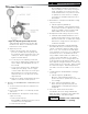
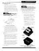
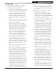
Figure 28: Cad Cell Location
9. Flame Failure
The CL boiler controls operate the burner
automatically. If for unknown reasons the
burner ceases to fire and the reset button on
the primary control has tripped, the burner
has experienced ignition failure. Refer to Oil
Primary Control features, Paragraph I, Step 2
of this Section and Section IX, Troubleshooting,
Paragraph B. If the failure re-occurs, call your
heating contractor immediately before pressing
the reset button.
WARNING
DO NOT attempt to start the
burner when excess oil has accumulated,
when the boiler is full of vapor, or when the
combustion chamber is very hot.
1. Check thermostat operation. Raise and lower
thermostat setting as required to start and stop
burner.
WARNING
Before installation of the
boiler is considered complete, the operation of
all boiler controls must be checked, particularly
the primary control and high limit control.
2. Verify Oil Primary Control features using
procedures outlined in Instructions furnished
with control or instructions as follows:
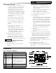
a. GeniSys 7505 Control Features, see Figure
29.
i. The GeniSys 7505 is a microprocessor-
based control. The indicator light
provides diagnostic information for
lockout, recycling and cad cell status.
There is a manual reset button to exit
the Lockout Mode.
ii. Pump Priming Cycle: To facilitate
purging air from the oil lines and filters,
the 7505 can be placed in a purge
routine by:
• After the burner starts, press and hold
the reset button for 15 seconds until
the yellow light turns on. This
indicates that the button has been
held long enough.
Figure 29: GeniSys 7505 Oil Primary Terminals,
LED's and Reset Button
10. Cad Cell Location and Service. The burner
is supplied with a cadmium sulfide flame
detector mounted at the factory, mounted on
the bottom of the electronic ignitor. See Figure
28. To service cad cell or to replace the plug
in portion, swing open the ignitor. After service
is complete, be sure to fasten down the ignitor.
H. CHECK FOR CLEAN CUT OFF OF
BURNER.
1. Air in the oil line between fuel unit and nozzle
will compress when burner is on and will
expand when burner stops, causing oil to
squirt from nozzle at low pressure as burner
slows down and causing nozzle to drip after
burner stops. Usually cycling the burner
operation about 5 to 10 times will rid oil line of
this air.
2. If nozzle continues to drip, repeat Paragraph
H, Step 1 above. If this does not stop the
dripping, remove cut-off valve and seat, and
wipe both with a clean cloth until clean, then
replace and readjust oil pressure. If dripping
or after burn persist replace fuel pump.
I. TEST CONTROLS.
5 System Start-Up (continued)